Download
1 / 19
190 likes | 482 Vues
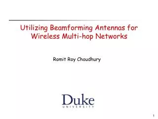
Coded Transmit Macrodiversity: Block Space-Time Codes over Distributed Antennas. Yipeng Tang and Matthew Valenti Lane Dept. of Comp. Sci. & Elect. Engg. West Virginia University mvalenti@wvu.edu. Overview. Block Space Time Codes Coded Transmit Macrodiversity

E N D
Coded Transmit Macrodiversity:Block Space-Time Codesover Distributed Antennas Yipeng Tang and Matthew Valenti Lane Dept. of Comp. Sci. & Elect. Engg. West Virginia University mvalenti@wvu.edu
Overview • Block Space Time Codes • Coded Transmit Macrodiversity • Space-time codes with widely separated antennas • Simulation Results • 2-antenna case • 3-antenna case • Both 60 and 120 degree sectorized antennas
Block Space Time Codes • The original STC were trellis based. • Tarokh 1998. • Shifted burden of diversity from receiver to transmitter. • Rather complex. • Block space time codes later emerged as a lower complexity alternative. • Block STC has no memory. • Symbol-in, symbol out. • Simple decoding structure.
Advantages and Disadvantages of Block STC • Advantages: • Space-time block coding utilizes multiple antennas to create spatial diversity, this allows a system to have better performance in a fading environment. • Good performance with minimal decoding complexity. • Can achieve maximum diversity gain equivalent to space-time trellis codes. • Receivers that use only linear processing. • Disadvantages: • Does not have as much coding gain as space-time trellis codes. • Can not always achieve the maximum data rates allowed by the general theory of space-time codes.
STC encoder X1 -X2* Ant 1 X1 X2 X2 X1* Ant 2 0 T 2T 0 T 2T Data Diagram of Block STC Transmission Fading c Data y x STC encoder r STC decoder Modulation AWGN Encoder matrix: Rate: 1/2
Block STC decoder • Each symbol in a block is decoded separately by minimizing the metric • The decoder outputs the hard-decisions on the data. • The more TXs and RXs the system has, the better performance the system can achieve.
Decoding Block STC The received signals are: In order to minimize it is equivalent to minimize By using: we have: and Since |x1|=|x2| (PSK), we can get:
Performance of Block STC Two transmit antenna system has around 18 dB coding gain while three transmit antenna system has around 25 dB coding gain. Most of diversity has been achieved just by two transmit antenna. back
Coded transmit Macrodiversity • Previous research has only considered the case that all of the transmit antennas are located in the same general location. • At a single base station in a cellular system. • Microdiversity. • Spatial correlation is an issue. • We consider combination of macrodiversity with block STC. • Macrodiversity: Antennas are far apart. • The array consists of the antennas of adjacent base stations. • For edge excited cells with 120 or 60 degree sectorized antennas, can use the three base stations at the corner of the cell.
Assumptions • Power control. • We assume that each of the antennas transmits with the same power. • TX power is controlled by closest base station. • However, due to different path lengths, the received signal powers will be different. • Depends on geometry and path loss exponent (n). • The best way to allocate power is an open problem. • Synchronization. • The received signals are not phase synchronized. • However, we assume the signals are time synchronous. • i.e. aligned in time. • This may not be an accurate assumption.
TX1 TX2 RX d1 d2 Two antenna system Normalized distances: Average received power at mobile station is:
Performance: Two transmit antenna system When the mobile station is close to either of the base station (to achieve the same BER), it requires more signal power than if it is halfway between the two transmit antennas. Performance is the best at location 0.5 which is exactly halfway between the two transmit antennas. Why? The center has the best diversity advantage.
TX1 RX TX3 TX2 Three transmit antenna system:Edge-excited Cell For the downlink, space time codes are transmitted from three base stations and received by one receive antenna in the mobile station. Encoder matrix is: Edge-excited
120-degree sectorized antenna • Each antenna transmits over a 120-degree sector. A O C B Three base stations are located in A, B and C, where the highest required SNR values are. The center of the cell is O, where the lowest required SNR is. The BER is 10-3.
120-degree system Performance Shown is the received SNR required to achieve a BER of 10-3 Again performance is best at center of cell. -Best diversity advantage. -Highest total SNR.
60-degree sectorized antenna • Three base stations are located on the corners of an equalateral triangle, and the block STC with encoder matrix G3 for the downlink communications is simulated. A O B C Three base stations are located in A, B and C, where the highest SNR values are. The center of the cell is in O, where the lowest SNR is.
60-degree system performance Shown is the received SNR required to achieve a BER of 10-3 Again performance is best at center of cell. Performance remains good at the midpoint between any two antennas.
Performance Comparison • 120-degree system has better trunking efficiency, and less frequent handoff. • 60-degree system has better energy efficiency, and larger system capacity. • Why? • Consider mobile at location x • With 120-degree sectorization is served by A-B-C • With 60-degree sectorization is served by A-B-D • D is closer than C. D A B C
Conclusion • There’s no reason that the antennas in a STC system must all be in the same general location. • Spread the antennas out! • The antennas could be located at different base stations. • Macrodiversity not microdiversity. • This improves coverage in areas that are far from base stations. • Could use three base stations and either 120 or 60 degree sectorized antennas. • Future work • Optimal power allocation strategies. • Impact of channel estimation. • Coping with signals that are not time-synchronous.