Download
1 / 26
260 likes | 480 Vues
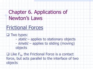
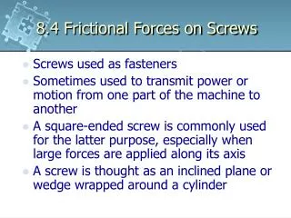
8.4 Frictional Forces on Screws. Screws used as fasteners Sometimes used to transmit power or motion from one part of the machine to another A square-ended screw is commonly used for the latter purpose, especially when large forces are applied along its axis

E N D
8.4 Frictional Forces on Screws • Screws used as fasteners • Sometimes used to transmit power or motion from one part of the machine to another • A square-ended screw is commonly used for the latter purpose, especially when large forces are applied along its axis • A screw is thought as an inclined plane or wedge wrapped around a cylinder
8.4 Frictional Forces on Screws • A nut initially at A on the screw will move up to B when rotated 360° around the screw • This rotation is equivalent to translating the nut up an inclined plane of height l and length 2πr, where r is the mean radius of the head
8.4 Frictional Forces on Screws • The rise l for a single revolution is referred to as the lead of the screw, where the lead angle is given by θ = tan-1 (l/2πr)
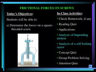
8.4 Frictional Forces on Screws Frictional Analysis • When a screw is subjected to large axial loads, the frictional forces developed on the thread become important to determine the moment M* needed to turn the screw • Consider the square-threaded jack which supports vertical load W
8.4 Frictional Forces on Screws Upward Screw Motion • Relative forces of the jack to this load are distributed over the circumference of the screw thread in contact with the screw hole in the jack, that is, within the region h • For simplicity, the thread can represented by a simple block resting on an inclined plane having screw’s lead angle θ
8.4 Frictional Forces on Screws Upward Screw Motion • The inclined plane represents the inside supporting thread of the jack base • 3 forces act on the block or screw • Force W is the total axial load applied to the screw • Horizontal force S is caused by the applied moment M such that by summing the moments about the axis of the screw, M = Sr where r is the screw’s mean radius
8.4 Frictional Forces on Screws Upward Screw Motion • As a result of W and S, the inclined plane exerts a resultant R on the block, which is shown to have components acting normal, N, and tangent F, to the contacting surfaces
8.4 Frictional Forces on Screws Upward Screw Motion • Provided M is large, the screw and the block can either be brought to the verge of upward impending motion or motion can be occurring • R acts at an angle (θ + Φ) from the vertical Φ = tan-1 (F/N) = tan-1 (μN/N) = tan-1μ
8.4 Frictional Forces on Screws Upward Screw Motion • Apply equilibrium equations • Solving • M is the moment needed to cause upward impending motion of the screw provided
8.4 Frictional Forces on Screws Upward Screw Motion • If Φ is replaced by Φk = tan-1μk (angle of kinetic friction), a smaller value of M is needed to maintain uniform upwards motion of the screw
8.4 Frictional Forces on Screws Downward Screw Motion • If the surface of the screw is very slippery, the screw may rotate downward if the magnitude of the moment is reduced to say M’ < M • This causes the effect of M’ to become S’ • It requires the angle Φ to lie on the opposite side of the normal n to the plane supporting the block such as θ < Φ M’ = Wr tan(θ – Φ)
8.4 Frictional Forces on Screws Self Locking Screw • If the moment M (or its effect S) is removed, the screw will remain self-locking • It will support the load W by friction forces alone provided Φ ≥ θ • To show this, consider the necessary limiting case when Φ = θ • Vertical equilibrium is maintained since R is vertical and thus balances W
8.4 Frictional Forces on Screws Downward Screw Motion • When the surface of the screw is very rough, the screw will not rotate downwards • Instead, the direction of the applied moment must be reversed in order to cause the motion • S’’ is caused by the applied (reverse) moment M’’ M’’ = Wr tan(Φ – θ)
8.4 Frictional Forces on Screws Example 8.8 • The turnbuckle has a square thread with a mean radius of 5mm and a lead of 2mm. If the coefficient of static friction between the screw and the turnbuckle is μs = 0.25, determine the moment M that must be applied to draw the end screws closer together. Is the turnbuckle self-locking?
8.4 Frictional Forces on Screws View Free Body Diagram Solution • Since friction at two screws must be overcome, this requires • Solving • When the moment is removed, the turnbuckle will be self-locking
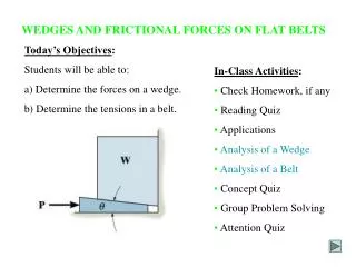
8.5 Frictional Forces on Flat Belts • Whenever belt drives or hand brakes are designed, it is necessary to determine the frictional forces developed between the belt and its contacting surfaces • Consider the flat belt which passes over a fixed curved surface such that the total angle of belt to surface contact in radians is β and the coefficient of friction between the two surfaces is μ
8.5 Frictional Forces on Flat Belts • Determine the tension T2 in the belt which is needed to pull the belt CCW over the surface and overcome both the frictional forces at the surface of contact and the known tension T1 • Obviously T2 > T1
8.5 Frictional Forces on Flat Belts Frictional Analysis • Consider FBD of the belt segment in contact with the surface • Normal force N and the frictional force F, acting at different points on the belt, vary both in magnitude and direction • Due to this unknown force distribution, analysis the problem by studying the forces acting on a differential element of the belt
8.5 Frictional Forces on Flat Belts Frictional Analysis • Consider FBD of an element having a length ds • Assuming either impending motion or motion of the belt, the magnitude of the frictional force dF = μ dN • This force opposes the sliding motion of the belt and thereby increases the magnitude of the tensile force acting in the belt by dT
8.5 Frictional Forces on Flat Belts Frictional Analysis • Applying equilibrium equations • Since dθ is of infinitesimal size, sin(θ/2) and cos (θ/2) can be replaced by dθ/2 and 1 respectively • Product of the two infinitesimals dT and dθ/2 may be neglected when compared to infinitesimals of the first order
8.5 Frictional Forces on Flat Belts Frictional Analysis Solving
8.5 Frictional Forces on Flat Belts Frictional Analysis • T2 is independent of the radius of the drum and instead, it is a function of the angle of belt to surface contact, β • This equation is valid for flat belts placed on any shape of contacting surface • For application, it is valid only when impending motion or motion occurs
8.5 Frictional Forces on Flat Belts Example 8.9 The maximum tension that can be developed In the cord is 500N. If the pulley at A is free to rotate and the coefficient of static friction at fixed drums B and C is μs = 0.25, determine the largest mass of cylinder that can be lifted by the cord. Assume that the force F applied at the end of the cord is directed vertically downward.
8.5 Frictional Forces on Flat Belts View Free Body Diagram Solution • Lifting the cylinder, which has a weight of W = mg, causes the cord to move CCW over the drums at B and C, hence, the maximum tension T2 in the cord occur at D • Thus, T2 = 500N • For section of the cord passing over the drum at B • 180° = π rad, angle of contact between the drum and the cord β = (135°/180°)π = 3/4π rad
8.5 Frictional Forces on Flat Belts Solution • Since the pulley at A is free to rotate, equilibrium requires that the tension in the cord remains the same on both sides of the pulley
8.5 Frictional Forces on Flat Belts Solution • For section of the cord passing over the drum at C W < 277.4N