Download
1 / 43
500 likes | 3.28k Vues
Its a report about summer training at UEM Delhi

E N D
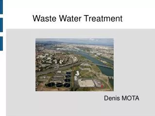
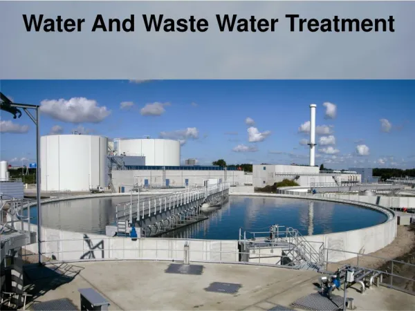
TRAINING REPORT ON WASTE WATER TREATMENT UEM ,India By:Kriti Goravala 352/07
ABOUT UEM UEM Group is an International Multi-disciplined Environmental Services Company specialized in providing Turn-key Design and Construction Services in the field of Water and Wastewater Treatment for Industries and Municipalities. UEM Group provides complete, single source services from Design, Engineering, and Supply of equipment/systems, Construction, Installation and Operation and Maintenance with full responsibility ad performance guarantees for Water and Wastewater Treatment facilities.It affiliates employ over 170 professionals in the disciplines of sanitary, environmental, water supply/distribution, structural, electrical, geo-technical, mechanical and other engineering disciplines along with field construction, fabrication and related personnel. UEM has installed more than 40 Sewage Treatment Plants of very large / medium / small capacities. Among the largest is a 182 MLD STP for Delhi Jal Board in India. The treatment system consists of Mechanical Screening, Grit Removal, Primary Clarifications, Aerobic Treatment with Aeration Tank and Clarifiers, Anaerobic Digesters with Gas Mixing for Primary & Secondary sludges, Gas utilization and Power Generation (1.2 MW) using Duel Fuel Gas Engine, Sludge Drying Beds, etc
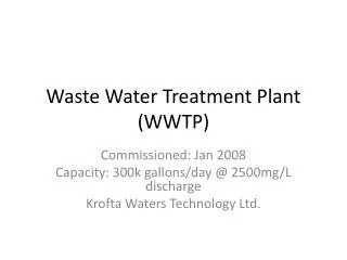
Purpose of The Plant • Basically the plant is setup to treat the waste water of the Common Wealth Village which is near the famous Akshardham Temple. • The sewage facilities being provided by DDA. • The treated water could be used for non-potable cosumption. • The membrane bio-reactor technology is new in India but has been developed a decade back and was used in foreign countries.
Salient Features of Plant • Zero discharge of Waste water. • Small Footprint thereby saving the prime land in the city. • 100%automation requiring minimum or NO manpower. • 200%power backup for uninterupted operations. • The plant on which is setup is the biggest one using MBR technology in INDIA. • Low sludge production is also there which is very desirable .
Plant General Information • Inlet works • Grit removal and screening • Biological Treatment • Membrane Treatment • Sludge Handling • Electrical And Control system • Odour control system
Technical Part of Plant The selection of a Treatment Process depends upon the following: • quality of the influent, • the degree of treatment required, i.e. the quality of treated water and the end use. In view of the above, we have specifically taken care of the overall system design with following consideration: • Aesthetics and Environment Friendliness • Consistent High Level Performance
Proposed Technology Fuelled by the growing demand of continuous high quality water under vastly variable operating conditions and treatment plants at sensitive locations and on Premium lands and with growing emphasis on Aesthetics, Environmental Friendliness and Space Savings, UEM has selected the modified Activated Sludge Process using MBR Technology and disinfection. for the Sewage Treatment (1MGD Flow)
DESIGN BASIS The Proposed Sewage Treatment Plant at near Akshardham is designed to treat the municipal sewage to effluent quality standards as stipulated by The Delhi Jal Board. The following are the main design parameters considered for the proposed Sewage Treatment Plant: • Treatment Capacity • Raw Sewage Quality and Quantity
VARIOUS DESIGN PARAMETERS Temperature………………………………18 0 C-40 0 C pH…………………………………………..7.0 – 7.6 Total Solids……………………………….773-1164mg/L Suspended Solids………………………..400 mg/L(200-300mg/L) Total BOD5 20 0 C……………………….250mg/L(116-263mg/L) Total COD ………………………………...247-750mg/L TKN………………………. ………………40 mg/l NH3………………………………………….25mg/L Oxygen Absorption……………………….53.6-77.8/l Total Alkanity………………………………305-470 mg/L Chlorides…………………………………..94-180 mg/L Oil & Grease………………………………10-18 mg/L Sp. Gravity of Grit…..…………………….2.5 Size Distribution of Particles in Raw Sewage………………….90% of particles are above 0.15mm Quantity of Grit (in raw sewage)…………0.1m3/million litre
PROCESS DESCRIPTION Primary Treatment • Inlet Chamber • Coarse screen Channels • Collection Sump
How sewage enters Raw sewage shall be delivered trough sewage network up to inlet chamber.From the inlet chamber it passes through screening,the raw sewage comes from the house hold wastes of the CWG village.It is then further sent to screening.
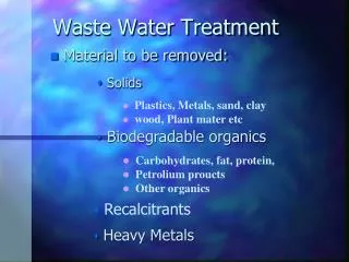
COARSE SCREEN CHANNELS Waste material such as : • Plastic bags • Rags • Other floating material • Etc which can removed by a mecahnical bar screens with 20mm opening size are provided.
COLLECTION SUMP • Screened sewage is then collected in the collection sump having a capacity of 31.5M(3) which is equivalent to 10 minutes of hydraulic retention at average flow. • Three nos. submersible pumps of 473M(3)/hr and two more submersibble pumps of 240M(3)/hr each with 18M head were provided to lift the sewage to grit separator.
GRIT SEPARATOR • Grit separator are provided to remove grit and sand particles from the sewage to avoid accumulation in the process units • Also to safeguard the various rotary equipments from abrasion. • Two aerated grit chambers are provided. From here sewage enters fine screen chamber
Dimensions: Distribution Chamber for Grit Chamber • Quantity : 1 No. • Detention Time : 180 sec (at Peak Flow) • Length : 4.0 m • Width : 2.5 m • Water Depth : 2.5 m • Free Board : 0.5 m
FINE SCREENS • Fine screens have an opening of 6mm. • These are used to remove floating particles. • Also to remove particles that might have escaped from grit separation chamber or coarse screen chamber. • Safeguard the various rotary equipments from abrasion.
BALANCING TANK Sewage enters into the balancing tank for equalization of flow and organic load. This results in enhancement of biological treatment as shock loadings are eliminated or minimized and pH is stabilized The balancing tank is kept in aerobic condition by the provision of diffusers. Air is supplied at a rate of 0.01m3/m3.min (1.25ft3/103gal.min). The unit is covered and trapped odour released is collected and treated in odour control system.
Dimensions of Balancing Tank : • Flow (Peak) : 473 m3/hr • Quantity : 1 No. • Detention Time : 6 hrs (at Peak Flow) • Dia : 31.0 m • Side Water Depth : 3.8 m • Free Board : 0.5 m • No. of Blowers : 3(2W+1S) • Blower Capacity : 931 m3/hr (Air requirement for Balancing • tank + Grit chamber) • No. of Diffuser : Lot • MOC : RCC Pumps Capacity : 100 m3/hr @ 10m Quantity : 3Nos.(2W+1S) Operating Hrs : 24Hrs
ULTRA FINE SCREENS 2 no mechanically cleaned ultra fine screens having an opening size of 1mm are provided to remove the finest of floating stuff like hair etcwhich are detremental to the operation and maintainance of MBR systems.
Dimensions: Screen • Flow (Peak) : 473 m3/hr • Quantity : 2 Nos. [1W (mechanical) +1S (manual)] • Clear Spacing : 6mm (mechanical), 10mm (manual) • Width : 700 mm • Dia of Drum : 500 mm
ANOXIC BASIN Mechanical fine screens (1W+1S) with 1mm opening are provided complete with compaction and washing arrangement prior to anoxic tank to remove any solids that might damage the membranes. Screened and degritted waste water is delivered to Anoxic basin from the inlet chamber where denitrification takes place. Denitrification is a conversion of nitrate, generated in and recycled from MBR’s, to nitrogen gas in the absence of oxygen and presence of suitable carbon source as an electron donor. This process is usually carried out by heterotrophic bacteria called as denitrifies. Carbon source is oxidized to synthesize cell mass using nitrates as an energy source. In this process apart from denitrification some lost alkalinity (3.57g/g of NO3-N reduced) is also recovered (approximately one-half the amount of alkalinity destroyed by nitrification) and hence sludge quality is improved.The consumption of BOD has the side benefit of reducing aeration requirements, thereby improving the overall energy performance of the system. Anoxic tanks will be provided with submersible mixers to keep the basin in mixed condition
Dimensions: Quantity : 2Nos. HRT : 1.6Hrs Volume : 150 m3 (each) Internal Recycle Rate : 4 Q MLSS : 8,000 mg/L RAS Pump: Capacity : 474 m3/hr @ 30ft Quantity : 4Nos.(2W+2S)
Denitrification: C10H19O3N + 10NO3- 5N2 + 10CO2 + 3H2O + NH3- + 10 OH- (Biodegradable Organic Matter in Wastewater)
PRE-AERATION BASIN Mixed liquor from the anoxic basins will be pumped, using recycle pumps, to pre-aeration basins, where air is supplied to provide oxygen for carbonaceous BOD removal and nitrification. In the presence of oxygen the autotrophic nitrifying bacteria oxidizes ammonical-nitrogen to nitrites and finally to nitrates. For each g of ammonia nitrogen converted 4.25g of O2 is utilized and 7.07g of alkalinity is removed. A DO concentration of >2mg/L is maintained for good working of Nitrifying bacteria
Nitrification: 2NH4+ + 3O2 2NO2- + 4H+ +2H2O (Nitrosomonas) (Nitrites) 2NO2+ + O2 2NO3- (Nitrobactor) (Nitrates) or NH4+ + 2O2 NO3- + 2H+ +H2O
Dimensions: • Quantity : 2Nos. • HRT : 4.4Hrs • Volume : 413 m3 (each) • MLSS : 8,000 mg/L • Blower Quantity : 3Nos. (2W+1S) • Blower Capacity : 198 scfm @5.2 psig
MBR BASINS • The partially stabilized mixed liquor from pre-aeration basins then flows by gravity into the MBR’s. • The separation of biomass from treated water using membranes not only provides filtered quality final effluent, offering possibilities of re-use, but also allows very high biomass mixed liquor suspended solids (MLSS) concentrations to be developed in the bioreactor without the detrimental effects usually associated with traditional settlement techniques
What is MBR MBR combines activated sludge treatment with a membrane liquid-solid separation process. The membrane component uses low pressure microfiltration or ultra filtration membranes and eliminates the need for clarification and tertiary filtration. The membranes are typically immersed in the aeration tank; however, some applications utilize a separate membrane tank. One of the key benefits of an MBR system is that it effectively overcomes the limitations associated with poor settling of sludge in conventional activated sludge (CAS) processes. The technology permits bioreactor operation with considerably higher mixed liquor suspended solids (MLSS) concentration than CAS systems, which are limited by sludge settling. The process is typically operated at MLSS in the range of 8,000–12,000 mg/L, while CAS are operated in the range of 2,000–3,000 mg/L. The elevated biomass concentration in the MBR process allows for very effective removal of both soluble and particulate biodegradable materials at higher loading rates. Thus increased sludge retention times, usually exceeding 15 days, ensure complete nitrification even in extremely cold weather.
Dimensions: • Quantity : 4basins • Surface Area : 0.8 m2/cartridge • HRT : 2.3Hrs • Volume : 117 m3/basin • MLSS : 10,000 mg/L • Blower Quantity : 6Nos. (4W+2S) • Blower Capacity : 654 cfm @4.4psig • Quantity : 5Nos.(4+1)
Membrane Chemical CIP (Cleaned in Place) System • The System includes a membrane cleaning system for periodic cleaning of the membranes. • The membrane units are by simply injecting the permeate line by, bleach for organic and citric / oxalic acid for inorganic substances. • The cleaning solution remains in the membrane for 1 to 3 hrs and then normal operation is resumed. • During a cleaning, few modules of Membrane is taken offline while the other modules of Membranes are operated at higher flux rates as required to meet plant demand.
DISINFECTION • The main treatment process removes a wide spectrum of bacteria from sewage. • The permeate will be collected in the disinfection tank via permeate pump where permeate will be subjected to chlorine dosing at a rate of 0.2lpm • Sodium hypochlorite can also be used.
TREATED WATER TANK The disinfected water is collected in treated water tank of RCC construction designed at average flow at retention of 12 hrs to be finally pumped for reuse. Dimensions: Treated Water Tank • Quantity : 1 No. • Detention Time : 12Hrs • Capacity : 2270 m3 • Length : 25.0m • Width : 23;Liquid Depth : 4.0m
SLUDGE THICKENER • Gravity Sludge Thickener shall be provided to handle the Primary Sludge produced during the course of sewage treatment. • Thickening is a procedure that is used to increase the solids fraction of sludge by removing a portion of the liquid fraction • This volume reduction obtained by sludge concentration shall be beneficial to subsequent treatment processes, such as digestion and dewatering. • Gravity thickening shall be accomplished in a tank similar in design to a conventional sedimentation tank.
Dimensions: Quantity : 1Nos. • Dia : 4.5 m • SWD : 3.0 m • Type : Gravity Centrifuge Feed Pump • Quantity : 2Nos.(1W+1S) • Capacity : 2.5m3/hr
SLUDGE DEWATERING EQUIPMENT • Sludge from sludge thickener is pumped by screw pumps to centrifuge for dewatering of sludge and to reduce it to spade-able concentration. • A poly electrolyte system dosing system is provided. Centrifuge shall be capable of handling sludge consisting of minimum 0.8% solids by weight. • The dewatered cake shall be based on minimum consistency of 25% by weight dry solids. • The centrifuge shall be solid bowl centrifuge of co-current/countercurrent design.
FILTRATE PUMP • A filtering device including a tank partially located below floor level having a filtrate compartment and a filter means interposed there between. • Reservoir means and an end suction centrifugal pump means both located substantially on floor level wherein conduit means selectively permits the filtrate level in the reservoir to maintain a positive pressure at the inlet of the pump when pump is shut off, and to neutralize the pressure differential between the filtrate compartment and the tank.
ODOUR CONTROL • The plant maintains various parameters for odour control .To maintain an odour free ambience in and around the STP ,odour control units are installed at various locations where the potential of odour is high . • Odorous gasses from these areas are collected and transmitted using centrifugal fans to the odour control towers. • The odourous gasses are passed through packed bed and simultaneously washed by a current of water. To maintain an odour free ambience in and around the STP,odour control units are installed at various locations wher the potentiaal of odour is high.Odorous gasses from these areas are collected and transmitted using centrifugal fans to the odour control towers . • The odorous gasses are passed through a packed bed and simultaneously washed by a counter current of water. • Depending upon the type of gas to be treated,appropriate dosage of sodium Hypochlorite or sodium Hydroxide is added to waste water.
ELECTRICAL & CONTROL EQUIPMENT • This STP has been equipped to run on state of SCADA system ,PLC,control panels,MCC’s,cabling panels ,wiring ,earthing,and plant lighting. • Power to the STP plant is fed from substation .The substation is equipped with total supply fed by BSES. • The plant is completely powered,monitored and controlled from the control rooms. • The control room is fully automatic.
CONCLUSION The plant is designed to provided good treatment.The plant provides the advantage of minimum footprint whilst maintaining the overall architectural and aesthetical requirements.Technically it utilizes a modern up to dete process that ensures a consistent high quality of treated effluent is used for various non-potable usages besides generating a very low quantity of biological sludge which can be used as a fertilizer landfill.