Download
1 / 37
860 likes | 2.47k Vues
Substation Monitoring System. Group 6 John Blackburn Steve Johnson Anish Raj Pant Devin King. Sponsored by BCI Technologies. Motivation . All group members were in the same power systems class.

E N D
Substation Monitoring System Group 6 John Blackburn Steve Johnson Anish Raj Pant Devin King Sponsored by BCI Technologies
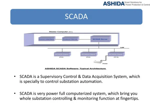
Motivation • All group members were in the same power systems class. • To become familiar with SCADA (Supervisory Control and Data Acquisition) – Used in the real-world to monitor power. • BCI Technologies sponsorship.
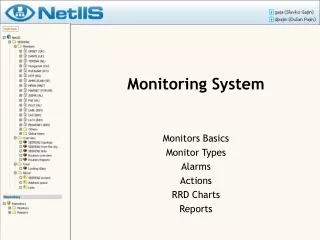
Goals and Objective • Monitor electrical values for a simulated power substation. • Open and close the relay remotely. • Check the status of the relay. • Send status messages wirelessly. • Easy to use graphic interface. • Device to be enclosed in a protective case with manual switch.
Requirements / Specifications • Maximum load current of 10A. • Station alarm with audible level of at least 70dB. • Wireless communication range of at least 30m. • Controller with at least 15 I/O pins. • A NEMA rated panel enclosure.
Microcontroller • PIC18F4550 • 40 pins • 13 A/D inputs • 18 GPIO’s • Wide Operating Voltage Range: 2V – 5.5V • Internal Oscillator : 31kHz – 8MHz
Modbus Protocol • A simple protocol data unit (PDU) independent of underlying communication layers. • Modbus is used in many devices such as: • PLC, HMI, Control Panels, Drivers, Motion Controls, and other I/O devices • To control and initiate remote operations. • Can be done on serial interfaces as well as TCP/IP. • We are using Modbus serial to do our communications.
Modbus Communication Stack Modbus Application Layer
Modbus cont. • Handshake type serial transmission • Modbus Message Transaction
Modbus cont. • Format written in Hex • Request • usually 8 bytes • A positive Response • The response function code = the requested function code. • An Exception Response • Error detected during processing. • Exception code = requested function code + 0x80h for the reason of the error. • The microcontroller must be programmed to accept the modbus library of functions and error exceptions.
Modbus cont. • Function code 03-Read Holding registers to access the data from our microcontroller. • Function code 06-Write Single Register to wirelessly control and receive the status of the relay.
Wireless communicationsSpecifications • Bi-directional communications • 3.3 to 5 DC operational voltage • Small form factor < 3”x3”x3” for panel • Small form factor < 2”x2”x2” for computer interface • Serial communications • Data transfer rate minimum of 50Kbps • Effective range of >30 meters
Wireless Communications • X-Bee RF module • Small form factor • ZigBee 802.15.4 standard • Decent range (100 meters) • Low power consumption (1 mW) • Data rate of (250 Kbps) • Mesh or point to point topology • Inexpensive ($19 from digi.com)
Serial and USB Explorers • Configuration of modules • Testing • Cost of $24 from Sparkfun.com
Testing of X-Bee Modules • Computer to computer test • HyperTerminal • Two X-Bee modules using RS232 and USB explorers
Testing of X-Bee Modules • Stand alone test • Using USB Explorer and stand-alone module and HyperTerminal • 3.3 volt power supply
X-Bee Adapter Kit • Connects via USB with FTDI cable • Onboard voltage regulator • Cost of $10 from Adafruit Industries
Energy Meter • ADE7753 • Single Phase • Voltage and current sensor inputs • Active, reactive, and apparent energy measurements, rms calculation on the voltage and current. • Serial interface
Energy Meter • VRMS accuracy: 0.5% • Analog input range: +/-32mV to +/- 500mV peak • Supply current: 7mA • IRMS accuracy: 0.5%
Current and Voltage Sensor • Current Transformer • CR8351-2000-N • Low Cost • 50Hz - 400Hz • Maximum primary current: 350A (RMS) Current Sensor Input Voltage Sensor Input
Power Supply • 12VDC to 5VDC • LM317T • Variable voltage regulator • 10K potentiometer for adjusting the output voltage • Capacitors to reduce voltage ripple
Liquid Crystal Display • Model Number: SSC2F16DLNW-S • Features: • 16 X 2 Display • Dimensions 3.13”(W) X 1.42”(H) X 0.53” (D) • 4-bit or 8-bit parallel interface • Standard Hitachi HD44780 equivalent controller. • LED backlight
Double Pole Double Throw Relay • Control the power usage • The relay will act as an overload device. • The microcontroller will be programmed to send a signal. • The relay will trip the alarm. • Easily mounted inside the panel.
Alarm • Piezo Buzzer – Audible alert if fault detected • 100dB • LED’s for relay status • Will sound when a fault is detected by the relay
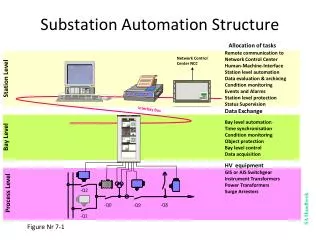
SCADA - ClearScada • High level Industrial software • Integrated Development environment using an Object Oriented database of information • Allows us to create an easy to use graphical interface. • Create all analog and digital points to be monitored. • Configure alarm limits to trip the breaker on an over-current condition or manually with the scripts written for the breaker buttons. • Difficult problem: connecting high level industry standard software back to small circuit design. • Software Demo License courtesy of BCI Technologies. (free)
SCADA cont. • The software is a development environment much like LabVIEW or Visio. • It must be customized, configured and programmed to your specific need or application. • It can be configured and programmed in a few different ways. • Scripting to run behind the buttons, so when they are pressed it will set the object to 1 or 0. • Structured Text Program – similar to a C program, our use is to write a 1 or 0 to the relay status register. • Function Block-our use is to break up to get the high byte or the low byte of an address or piece of information passed in.
SCADA cont. • Scripting Code written to close relay. • Function block to separate the high byte from the low byte for the 2 byte address in modbus protocol. This could also be used to read or write to a single bit in the byte.
Actual Panel • Stahlin Non-Metallic Enclosure • 16x14x8 in Temp. Rating: -40˚ F to 250 ˚ F • Nema 4x rating Industrial Grade • Cost $57 but donated by BCI Technologies
Project Budget • Most of the parts donated by BCI Technologies. • We have currently spent$200. • We are currently on trackwith the budget.