Download

1 / 51
981 likes | 2.14k Vues
Fatigue. Outline. Fatigue Initiation and growth mechanisms Stress-life fatigue analysis Strain-life fatigue analysis Component testing Fatigue crack growth Design and validation of medical device fatigue performance Statistics. Fatigue Concepts. Definition of Fatigue:

E N D
Outline Fatigue • Initiation and growth mechanisms • Stress-life fatigue analysis • Strain-life fatigue analysis • Component testing • Fatigue crack growth • Design and validation of medical device fatigue performance • Statistics
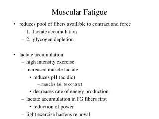
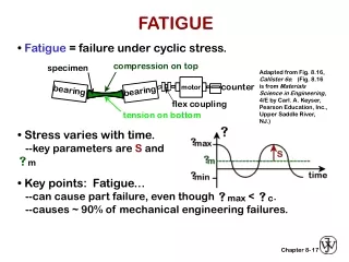
Fatigue Concepts Definition of Fatigue: • The process of progressive, localized permanent structural change that occurs in a material subjected to cyclic loading • Fatigue can and does occur at stresses well below a given material’s yield strength • The annual cost of fatigue of materials has been estimated to be about 3% of the US Gross National Product (from N.E. Dowling, Mechanical Behavior of Materials, Prentice-Hall, 1998, pg. 358.)
Fatigue Concepts The mechanism of fatigue crack initiation: • Requires local plastic deformation, usually at a stress concentration location or a properly oriented grain • Slip along slip bands- plane of maximum shear • Formation of intrusions and extrusions • Cracks form along slip planes
Fatigue Concepts Fatigue crack initiation: • Often occurs at local stress discontinuities: notches, voids, inclusions, etc. • Affected by surface preparation and roughness • In general, increased surface roughness decreases resistance to fatigue crack initiation • Affected by residual stresses • Affected by material strength, in general, the higher the tensile strength, the higher the resistance to fatigue
Fatigue Concepts Fatigue crack growth: • Literature focuses on striation-formation mechanisms in metals. Note – striations are frequently NOT observed on metal fracture surfaces after real-world (non-laboratory) fatigue: • Striations most obvious in very ductile metals • Striations only occur within a certain crack growth-rate “window” • Fracture surface damage from crack closure (rubbing) can remove striations • Fracture surface damage from corrosion can remove striations • A single striation can, but does not necessarily represent one cyclic event
Fatigue Concepts Striation formation model
Fatigue Concepts Design for Fatigue Prevention: • Stress-life approach • Strain-life approach • Fatigue crack propagation approach (LEFM-based damage tolerant design) • Component testing
Stress-Life Fatigue stress range, σr = σmax – σminstress amplitude, σa = (σmax – σmin)/2mean stress, σo = (σmax + σmin)/2Stress ratio, R = σmin/ σmax
Stress-Life Fatigue S-N behavior can also be expressed with a power-law equation (linear line on log-log plot): σa = true stress amplitude2Nf = reversals to failure (1cycle = 2 reversals)σ'f = fatigue strength coefficient (approximately equal to true fracture strength)b = fatigue strength exponent
Stress-Life Fatigue • How do you design a part if your R ratio (mean stress/strain) is different than your S-N data? • Use Goodman, Gerber, or Soderberg relations • Note that this mean stress/strain technique is not applicable to superelastic nitinol (to be discussed later)
Stress-Life Fatigue Line a = Soderberg relation: Sa = Scr(1-So/Sy)Line b = Modified Goodman relation: Sa = Scr(1-So/Su)Line c = Gerber relation: Sa = [Scr(1-So/Su)2]Line d = Goodman relation modified with σf
Stress-Life Fatigue • Soderberg relation is the most conservative • Goodman is frequently used for brittle metals, and is conservative for ductile metals • Gerber relation is good for ductile metals • Improved agreement for Goodman and Gerber using true fracture strength instead of ultimate tensile strength
Stress-Life Testing • Modification to Goodman relation suggested by Morrow, replace σu (ultimate tensile strength) with σ'f (fatigue strength coefficient) from the unnotched axial S-N curve for R=-1 • Results in improved agreement for ductile metals
Stress-Life Fatigue Generation of an S-N curve at non-zero mean stress: σar = fully reversed (R=-1) alternating stressσa = alternating stress at some mean stressσm = mean stressσ'f = fatigue strength coefficientb = fatigue strength exponent Nf = number of cycles to failure Allows the generation of S-N curves for different values of mean stress based on fully reversed S-N behavior
Stress-Life Fatigue Constant-life diagram for solution-treated and aged Ti-6Al-4V
Stress-Life Fatigue Variable amplitude loading: Palmgren-Miner Rule: ΣNj/Nfj = 1
Stress-Life Fatigue Variable amplitude loading: effect of periodic overstress into plastic region: Fatigue strength, no overstress Stress Amplitude Periodic overstress Nf = Cycles to Failure
Strain-Life Fatigue • More than just substituting strain for stress in lifetime testing • Uses cyclic stress-strain curve to obtain strain versus life • Elastic and plastic strain considered separately, then summed • Considers plastic deformation that may occur in localized regions (instead of nominal stresses and stress concentration factors as in stress-life)
Strain-Life Fatigue Most metals display metastable cyclic stress strain behavior when subjected to cyclic loading • Cyclic strain hardening • Cyclic strain softening
Strain-Life Fatigue Cyclic Strain Hardening:
Strain-Life Fatigue Cyclic Strain Softening
Strain-Life Fatigue Find Elastic Portion of equation: σa = true stress amplitude2Nf = reversals to failure (1cycle = 2 reversals)σ'f = fatigue strength coefficientb = fatigue-strength exponent
Strain-Life Fatigue Elastic portion of equation: Δεe = elastic component of cyclic strainE = elastic modulusσa = true stress amplitude2Nf = reversals to failureσ'f = fatigue-strength coefficientb = fatigue-strength exponent
Strain-Life Fatigue Determine plastic side of equation: Power law plastic strain-life relation established by Coffin and Manson independently in the 1950s: Δεp = plastic component of cyclic strainε'f = fatigue ductility coefficient 2Nf = reversals to failure c = fatigue-ductility exponent
Strain-Life Fatigue Coffin-Manson relation for strain-life fatigue
Strain-Life Fatigue Mean Stress/Strain Effects: Similar approach as with stress-life fatigue Allows generation of εa versus Nf at varying mean stress
Component Testing • Component fatigue testing is S-N or ε-N fatigue testing of many exemplar components to failure in order to determine/validate fatigue properties • For implantable medical devices, commonly use component fatigue testing to validate design • Advantage of component testing for medical devices is use of actual geometry, surface conditions, residual stresses • Component fatigue testing relies on principles of S-N and ε-N fatigue analysis • Medical device component fatigue validation also relies on finite element analysis to determine stresses and strains
Component Testing Examples of component fatigue testing: • ASTM F 382, Annex A2 – Standard Test Method for Determining the Bending Fatigue Properties of Metallic Bone Plates • Used as a means to characterize different bone plates • Cardiovascular implant testing – S-N • Cardiovascular implant durability testing – 400 to 600 million cycles, pass/fail • Note: pass/fail testing to 400 or 600 million cycles (10 years of life) does not characterize fatigue performance, safety factor or margin
Component Testing Example of Component Testing Process: Vascular Implant • Conduct deflection-life testing of device (includes finished surface conditions, sterilization, expansion, etc.) • Generate deflection-life curve • Use finite element (FE) analysis to convert deflections (or loads) to stress and strain • Generate S-N or ε-N curve • Conduct statistical analysis of data, typically generate 1st percentile, 95% confidence line • If mean stress/strain variation is a concern, generate Goodman-type relation • Conduct FE analysis of stresses or strains on device for conservative in-vivo condition, compare with fatigue performance to validate design
Fatigue Crack Growth • Damage tolerant design method • Analysis of growing cracks based on linear elastic fracture mechanics • Assume a structural component contains cracks, all smaller than the minimum detectable length (ad) • Ensure insufficient stress to cause minimum detectable crack to grow (fatigue threshold, ΔKth approach), or insufficient cycles to grow crack to critical length for fracture (ac) over lifetime • Aircraft, nuclear industries use approach where inspection intervals are much shorter than time required to grow from ad to ac.
ac Crack length, a da/dN ad Cycles, N Fatigue Crack Growth Fatigue crack growth under constant amplitude loading:
Fatigue Crack Growth Apply linear-elastic fracture mechanics to crack growth (Paul Paris – 1960s, from Boeing) General form: Apply to fatigue use stress range, Δσ: Units are ksi(in)1/2 or Mpa(m)1/2
Fatigue Crack Growth • Fatigue Crack Growth Regions: • Fatigue threshold region: ΔKth is the fatigue threshold, the asymptotic value of ΔK at which da/dN approaches zero • Power law region: da/dN = C(ΔK)m, where c=constant, m=slope • Near- ΔKIC region: static fracture mechanisms become intermixed with fatigue crack growth, growth rate departs from linear, power-law behavior
R= -1/2 R=0 R=1/2 da/dN R= -1 ΔK Fatigue Crack Growth Effect of mean stress on fatigue crack growth (typically described as the R ratio, σmin/σmax): Note: compressive stress does not contribute to crack growth except in very ductile materials –crack closure effects
10 example ΔKth 1 0 1 Fatigue Crack Growth Effects of stress ratio (R) on ΔKth: ΔKth is highest near R=O, typical ΔKth values range from 1 to 15 ksi(in)1/2 R
Fatigue Crack Growth Limitations of da/dN technique for medical devices: • Plasticity: if plastic zone ahead of crack is very large compared to specimen or component thickness, linear-elastic fracture mechanics may not apply. Given small sizes of many devices, needs to be examined. • Minimum detectable crack/flaw size for ΔKth may be impractical/too costly to detect • Small crack behavior: if a crack is sufficiently small, it can interact with the microstructure and grow faster than predicted by da/dN versus ΔK
Fatigue Crack Growth Small v. Short cracks: • Small cracks have dimensions on the microstructural scale – e.g. grain size • Short cracks have one dimension that is large compared to the microstructure
Fatigue Crack Growth Small crack da/dN v. ΔK behavior:
Statistics in Fatigue “There are three kinds of lies: lies, damned lies and statistics.”- Mark Twain • Statistics are important! • Durability testing statistics are easy, testing involving cycles-to-failure requires more sophistication • Fatigue testing (to failure) is well known for significant data scatter • Statistics should be used to ensure results are significant with confidence
Statistical Analysis of Test Data • Characterization of strain-life or stress-life relationship • Choice of parametric regression model • Evaluation of goodness-of-fit • Estimates and confidence bounds • Robustness of conclusions • Run-outs (specimens surviving to end of test) • Treat as censored failure times using maximum likelihood methods • Do not ignore or count as failures
Statistical Regression Models • Common choices • Lognormal • Weibull • Gumbel (smallest extreme value) • Example—lognormal model: log(cycles) = a + b*log(strain) + error (a = intercept, b = slope)
Checking Adequacy of Chosen Model • Residual=Difference between observed value and value predicted from model • Graphical methods • Probability plots of residuals • Goodness-of-fit statistics • Summary measures calculated from residuals
Estimates and Confidence Bounds • Quantities of interest at design strain/stress • Median life • Percentile life (e.g., 5th) • Mean life • Confidence bounds express uncertainty associated with estimated fatigue life