FATIGUE
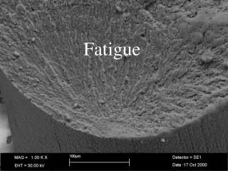
FATIGUE. Ship Break. BOLT FAILURE. . . BEACH MARKS. Beach Marks of FATIGUE. . Examples of Bolt Failures M24 Engine Mounting Bolt Failure. Failure due to repeatedly applied load is known as Fatigue.

FATIGUE
E N D
Presentation Transcript
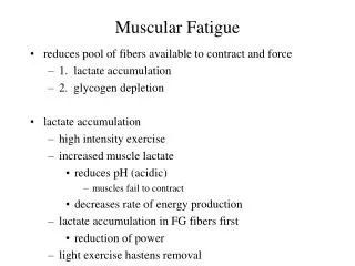
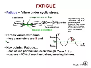
Failure due to repeatedly applied load is known as Fatigue. • The physical effect of a repeated load on a material is different from the static load. • Failure always being brittle fracture regardless of whether the material is brittle or ductile. • Mostly fatigue failure occur at stress well below the static elastic strength of the material.
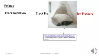
Fatigue • It has long been known that a component subjected to fluctuating stresses may fail at stress levels much lower than its monotonic fracture strength, due to a process called Fatigue. • Fatigue is an insidious time-dependent type of failure which can occur without any obvious warning. It is believed that more than 95 % of all mechanical failures can be attributed to fatigue. There are normally three distinct stages in the fatigue failure of a component, namely: Crack Initiation, Incremental Crack Growth, and the Final Fracture.
Fatigue • Introduction : • In several applications, components have to withstand different kinds of load at different times . • Materials subjected to these fluctuating or repeated load tends to show a behavior which is different from what they show under steady loads.
Fatigue occurs at stress well within the ordinary elastic range as measured in the static tension test. • Fracture resulting from fatigue is very difficult to predict and hence a good understanding of fatgue behavior is very important.
Types of fatigue loading: • 1.Completely reversed cycle of stress: • 2. repeated stress cycles • 3. irregular or random stress cycle:
Completely reversed cycle of stress: • Illustrates the type of fatigue loading where a member is subjected to opposite loads alternately with a means of zero. • For example bending of steel wire continuously in either direction leads to alternate tensile and compressive stresses on its surface layers and failure fatigue.
If the applied load changes from any magnitude in one direction to the same magnitude in the opposite direction, the loading is termed completely reversed,
Repeated stress cycles: • Type of fatigue loading where a member is subjected to only tension but to various degrees. • A spring subjected to repeated tension as in a toy would lead to fatigue failure.
Irregular or random stress cycle: • This type of fatigue loading where a member could be subjected to irregular loads just as in • the case of an aircraft wing subjected to wind loads.
i.e if the load changes from one magnitude to another (the direction does not necessarily change), the load is said to be fluctuating load.
Stages of fatigue failure • consider a ductile material which is subjected to simple alternating tensile and compressive stresses. • Failure by fatigue is found to take place in three stages: • i) Crack nucleation • ii) Crack growth • iii) Fracture
Crack nucleation: During the first few cycles of loading, localized changes take place in the structure at various places within the material. These changes lead to the formation of submicroscopic cracks.
Low Cycle Fatigue • Based on the LCF local strain philosophy, fatigue cracks initiate as a result of repeated plastic strain cycling at the locations of maximum strain concentration.
These cracks are usually formed at the surface of the specimen. There are several theories like orowans theory, cottell & hull theory etc, which explain the mechanism of crack nucleation.
Crack growth: • The submicroscopic cracks formed grow as the cycles of loading continue • and become microscopic cracks.
Fatigue Crack Propagation • If a crack exists in the component before it goes into service, for example due to weld fabrication or from some other cause, the ‘initiation’ stage is by-passed and the fatigue failure process is taken up entirely with incremental growth and final fracture.
Most fatigue failures in practice are in the low stress region, much less than the yield stress, where the LEFM is likely to be valid. Hence, the LEFM principles can be applied to predict incremental fatigue crack propagation
Fracture: When critical size is reached, the cark propagates. The are of cross-section supporting the load gets reduced thus increasing the stress value and finally occurs.
Classical Fatigue • The classical approach to fatigue, also referred to as Stress Controlled Fatigue or High Cycle Fatigue (HCF), through S/N or Wöhler diagrams, • .
In order to determine the strength of materials under the action of fatigue loads, specimens with polished surfaces are subjected to repeated or varying loads of specified magnitude while the stress reversals are counted up to the destruction point. • The number of the stress cycles to failure can be approximated by the WOHLER or S-N DIAGRAM,
Fatigue properties : • Fatigue life (N): it is total number of cycles are required to bring about final fracture in a specimen at a given stress. • Fatigue life for a given condition is a property of the individual specimen • and is arrived at after testing a number of specimens at the same stress.
Fatigue life for P % survival (Np) It is fatigue life for which P percent of samples tested have a longer life than the rest. • For example, N90 is the fatigue life for which 90% of the samples would be expected to survive and 10% to fail at a particular stress.
Median fatigue life: • it is fatigue life for which 50 % of the population of samples fail • and the other 50 % survive at a particular stress.
Fatigue strength (σn) • It is stress at which a material can withstand repeatedly N number of cycles before failure. • OR it is the strength of a material for a particular fatigue life.
Fatigue limit or Endurance limit (σE): • it is stress below which a material will not fail for any number of cycles. • For ferrous materials it is approximately half of the ultimate tensile strength. • For non-ferrous metal since there is no fatigue limit.
Endurance limit is taken to be the stress at which it endures, N number of cycles without failure .N is usually taken as 5 x 10⁸ cycles for non-ferrous metals.
Factors affecting fatigue: • Effect of stress concentration 2) Size effect: 3) Surface Roughness: 4) Surface Residual Stress: 5) Effect of temperature: 6) Effect of metallurgical variables;
Factors affecting fatigue: • 1) EFFECT OF STRESS CONCENTRATION • It is most responsible for the majority of fatigue failures • All m/c elements contain stress raisers like fillets, key ways, screw threads, porosity etc. fatigue cracks are nucleated in the region of such geometrical irregularities.
The actual effectiveness of stress concentration is measured by the fatigue strength reduction factor Kf Kf = σn / σnI σn = the fatigue strength of a member without any stress concentration σnI = the fatigue strength of the same member with the specified stress concentration.
fatigue failure by stress concentration can be minimized by • reducing the avoidable stress-raisers • careful design and • the prevention of stress raisers by careful machining and fabrication.
2) SIZE EFFECT: The strength of large members is lower than that of small specimens. This may be due to two reasons. The larger member will have a larger distribution of weak points than the smaller one and on an average, fails at a lower stress. Larger members have larger surface Ares. This is important because the imperfections that cause fatigue failure are usually at the surface.
Effect of size: Increasing the size (especially section thickness) results in larger surface area and creation of stresses. This factor leads to increase in the probability of crack initiation. This factor must be kept in mind while designing large sized components.
3) SURFACE ROUGHNESS: • almost all fatigue cracks nucleate at the surface of the members. • The conditions of the surface roughness and surface oxidation or corrosion are very important. • Experiments have shown that different surface finishes of the same material will show different fatigue strength.
Methods which Improve the surface finish and those which introduce compressive stresses on the surface will improve the fatigue strength. • Smoothly polished specimens have higher fatigue strength. Surface treatments. Fatigue cracks initiate at free surface, treatments can be significant Plating, thermal or mechanical means to induce residual stress
4) SURFACE RESIDUAL STRESS: • Residual stresses are nothing but locked up stresses which are present in a part even when it is not subjected to an external force. • Residual stresses arise during casting or during cold working when the plastic deformation would not be uniform throughout the cross section of the part.
Compressive residual stresses are beneficial, tension is detrimental Residual stresses not permanent, can be relaxed (temp., overload)
Shot Peening• Surface of component blasted with high velocity steel or glass beads• Core of material in residual tension, surface in residual compression• Easily used on odd shaped parts, but leaves surface dimpling