Download
1 / 23
230 likes | 389 Vues
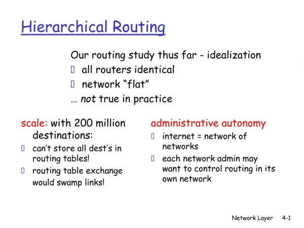
Hierarchical Routing. Problem: as size of network grows, routing table, complexity grows millions of nodes (hosts, routers) in Internet Solution: hierarchically aggregate nodes into "regions" (domain) node have full knowledge of routes, topological structure within region

E N D
Hierarchical Routing Problem: as size of network grows, routing table, complexity grows • millions of nodes (hosts, routers) in Internet Solution: hierarchically aggregate nodes into "regions" (domain) • node have full knowledge of routes, topological structure within region • one (or more) nodes in region responsible for routing to the outside Teminology: • intradomain routing: within domain • interdomain routing: between domains • autonomous system (AS): domain, region, administrative domain • gateway: routes to/from domain, a.k.a. border router
Hierarchical Routing (cont) Three domains: A, B, C A.a, A.b A.c run interdomain routing protocol A.c, B.a, B.b, C.a run intradomain routing protocol among themselves
Different routing protocols can be used for interdomain and intradomain routing A.a routing table: A look inside A.c: Hierarchical Routing (cont)
Hosts and routers Hosts (end systems) typically perform no routing • start packets on their way • send packets to nearest router Q: how do hosts learn identity of nearby router: • A1: IP address of router hard-coded into file (see /etc/networks on many UNIX systems) • A2: router discovery: RFC 1256 • router periodically broadcasts its existence to attached hosts • host (on startup) broadcasts query (who is my router) on attached links/LANs
Fields in IP packet: version number: (of IP protocol), current version is 4, new version is 6 header length: because of options, length of header is variable TOS: not used, idea was to allow different levels of reliability, real-time, etc packet length: header plus data identifier: used with IP fragmentation to identify fragments belonging to same original IP packet flags: 2 bits: do not fragment, more fragments fragmentation offset: if this a fragment, where it belongs in original packet time-to-live: decremented by each router, so a packet will not loop forever in the net protocol: which upper layer protocol to demultiplex to. See RFC 1700 header checksum: recomputed at each hop, as TTL changes source, dest IP address: of original sender, and eventual recipient Network Layer Case Study: the Internet
IP fragmentation and Reassembly • transport layer packet may be too big to send in single IP packet • underlying data link protocol will constraint maximum IP length • fragmentation: IP packet divided into fragments by IP • each fragment becomes its own IP packet • each address has same identifier, source, destination address • fragment offset gives offset of data from start of original packet • more fragment bit: 0 means last bit in this fragment • fragments not reassembled until final destination
Internet Intradomain Routing: RIP RIP: Routing Information Protocol, uses distance vector algorithm, with link costs of 1 • shortest path • routing table sent to neighbors every 30 seconds, or when route costs change Implemented as a daemon (user-level process) • communicates with other attached router using UDP packets • note: UDP packets can be lost! • if route via neighbor not updated in 3 minutes, timeout route (set cost to infinity) • called routed on UNIX systems
A RIP routing table Example table taken from freya.cs.umass.edu: ~ netstat -rn (note: on freya.cs.umass.edu)
Internet Intradomain Routing: OSPF OSPF: open shortest path first • open: a published standard (RFC 1247) • interior gateway protocol: for intradomain outing within an autonomous system (AS) • uses link state algorithm to determine routes • each outgoing link (interface) assigned dimensionless cost • different cost can be used for different TOS • load balancing: with several equal-cost-paths to destination, will distribute load across both paths Support for hierarchy: • autonomous system divided into "areas" • one area designated "backbone" • area border routers in backbone route between areas • other routers in backbone also • AS boundary router talks to outside world
Intra-area routing: never cross backbone To get from one area to another: source area -> backbone -> destination area area router:red boundary router:blue Internet Intradomain Routing: OSPF (cont)
Interdomain Internet Routing: BGP BGP: Border Gateway Protocol • routing between nodes in different autonomous systems (i.e., routing between networks) • RFC 1267, 1268 • uses a distance verctor approach Policy-Based Routing • rather than costs to destinations, BGP routers exchange full path information (networks crossed) to destination router can decide on policy basis which route to take • e.g. "traffic from my AS should not cross AS's a,b,c,d" • BGP implementation: • implemented as a daemon (user-level process) • communicates with other BGP routers using TCP
ICMP: Internet Message Control Protocol • used to communicate network-level error conditions and info to IP/TCP/UDP protocols or user processes • often considered part of IP, but • ICMP message sent within IP datagram • IP demultiplexes up to ICMP using IP protocol field • ICMP message contains IP header and first 8 bytes of IP contents that causes ICMP mesage to be generated
Changes to Ipv4: 128 bit addresses (so we don't run out of IP addresses) header simplification (faster processing) more support for type of service priorities flow identifier: identifiy packets in a connection security Notes: no fragmentation in network packet too big generates ICMP error to source source fragmentation via extension header no checksum (already done at transport and data link layer) IPv6: next generation IP
Transitioning from IPv4 to IPv6 Internet too big for "flag day": • can't turn off all IP routers, install IPv6 and reboot • IPv4 nodes will be legacy • IPv6 nodes can route IPv4 packets • IPv4 nodes can not route IPv6 packets Tunneling: • source and destination speak network protocol X • physically intermediate nodes speak network protocol Y • source takes protocol X packet, sticks it inside (encapsulates) protocol Y packet • intermediate nodes route using protocol Y • destination receives packet using protocol Y, removes protocol X packet • network between source and destination looks like a single link to protocol X
Case Study: ATM Network Layer • ATM: packet (cell) format: • UNI: user-network interface (host-to-switch) • NNI: network-network interface (switch-to-switch) • GFC: generic flow control (unused) • VPI: virtual path identifier • VCI: virtual circuit identifer • VPI and VCI together a call/connection identifier • PTI: payload type: 3 bits • 111: RM cell (recall RM congestion control) • 000: user cell • 010: user cell, congestion experienced (recall EFCI) • CLP: cell loss priority (1 bit) • priority bit for discarding • HEC: header error correction • DATA: 48 bytes of data
Observations about ATM Cell • very small • reflecting telephony origins • 48 bytes a compromise, halfway 64 and 32 • no explicit source/destination address • VCI/VPI used instead • faster switching (VPI/VCI can index into table) • 28 bit VPI/VCI for switching instead of 128 bit IP address in IPv6 (savings) • fixed length for faster switching • minimal priority
ATM networks: Virtual-circuit Oriented • VCI/VPI together identify call • multiple calls (VCI) bundled into same VP • network can switch on VP basis only • less state (network only sees VP's) • all VC's in VP follow same path
Connection Setup in ATM • messages ("signaling") used to setup up call through network • state info (VP switching info - which output line to switch incoming VC) set up in switches • meaning of call setup messages:
ATM Call Setup (cont) Observations: • unlike Internet, switches involved in call setup • state creation • ACKing between switches • wait one RTT before sending data • unlike UDP • same as TCP • what if connection breaks? • other switches must remove state • ATM standard does not specify a routing protocol
Input interface cards: physical layer processing memory buffers to hold incoming packet Switch fabric: to move packets from input to output Output interface cards: memory buffers to hold outgoing packets physical layer processing Control processor: routing table updates, supervisory (management) functions will typically not touch the packets being switched Switches and Routers: What's Inside
Switching Fabrics Two popular ways to switch: • switching via memory: input line ports write to memory, output ports read from memory • switching via a bus: bus (backplane) connects input and output ports • e.g.: Cisco AGS+ has 533 Mbps backblane bus
Network Layer: Summary Network service: datagram versus VC Theory of routing protocols • link state and distance vector • multicast • broadcasting Case studies: • Internet • IPv4, IPv6 • protocols for exchanging routing information: RIP, OSPF, BGP • ATM