Final Exam Performance Insights and Upcoming Course Projects Overview
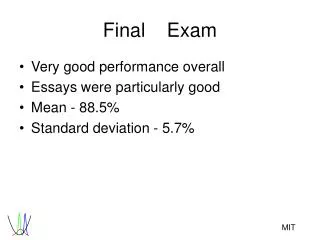
The final exam results demonstrate a very good overall performance, with an average score of 88.5% and essays notably strong. Homework scores for HW#8 and HW#9 averaged 96.1% and 94.9%, respectively. Moving forward, the main objective is to complete term projects, contributing 30% to the overall grade. Class sessions will alternate between new topics and consultations, focusing on tolerance design and robust design principles. Final projects are expected to represent around 30 hours of effort, with grading based on the written report and oral presentation quality.

Final Exam Performance Insights and Upcoming Course Projects Overview
E N D
Presentation Transcript
Final Exam • Very good performance overall • Essays were particularly good • Mean - 88.5% • Standard deviation - 5.7%
Homework • HW#8 • Mean = 96.1 • Standard Deviation = 7.4 • HW#9 • Mean = 94.9 • Standard Deviation = 5.5
The Remainder of the Course • Primary mission -- Complete your term projects • Secondary mission -- Cover topics of interest • 70% of your grades are set (term project = 30%) • Class sessions (half new topics / half consultation) • Tolerance Design / Projects • Mahalanobis Taguchi System / Projects • Conceptual Robust Design / Projects • Final Project Presentations
Expectations on Final Project • Should represent ~30 hours of effort • Options • Full robust design effort • Planning phase only • Post mortem analysis of a previous effort • Study of an advanced topic in robust design • Other possibilities with permission
Grading of the Final Project • 75% Written report • 25% Oral presentation • Grading criteria include • Impact and significance of the results • Quality of the planning and analysis • Clarity of technical exposition
Tolerance Design The Interface Between Design and Manufacture
Outline • History of tolerances • Tolerancing standards • Tolerance analysis • Tolerance design • Taguchi’s approach • Case study
History of Tolerances • pre 1800 -- Craft production systems • 1800 -- Invention of machine tools & the English • System of manufacture • 1850 -- Interchangeability of components & the American system of manufacture Jaikumar, Ramachandran. From Filing and Fitting to Flexible Manufacture, 1988.
Craft Production • Drawings communicated rough proportion and function • Drawings carried no specifications or dimensions • Production involved the master, the model, and calipers
The English System • Greater precision in machine tools • General purpose machines • Maudslay invents the slide rest • Accurate measuring instruments • Micrometers accurate to 0.001 inch • Engineering drawings • Monge “La Geometrie Descriptive” • Orthographic views and dimensioning • Parts made to fit to one another • Focus on perfection of fit
The American System • Interchangeability required for field service of weapons • Focus on management of clearances • Go-no go gauges employed to ensure fit • Allowed parts to be made in large lots Go - no go gauges Go -no go gauges
Tolerances on Drawings • Binary acceptance criteria • Multiple quality characteristics • All criteria must be met (dominance)
Basic Tolerancing Principlesref. ANSI Y14.5M • Each dimension must have a tolerance • Dimensions of size, form, and location must be complete • No more dimensions than necessary shall be given • Dimensions should not be subject to more than one interpretation • Do not specify manufacturing method
Tolerance AnalysisProbabilistic Approaches • Worst case stack up • Root sum of squares • Numerical integration • Monte Carlo simulation
Tolerance Analysis Problem 1.0”± 0.05” • Extruded aluminum bar stock • Cut two pieces • Stacked end to end • What is the probability that the stack will fit in this bracket? 1.0”± 0.1” 2.2”± 0.1”
Specifying Tolerances toMinimize Required Precision • How should this part be dimensioned? • How is optimal dimensioning determined by function?
Tolerance AnalysisGeometric / Kinematic Issues • Will these parts mate? • Solution approaches • Kinematic modeling • Assembly simulation
Variation Systems Analysis You supply geometry You define distributions Software provides: Variance Defect rate Pareto diagram
Computer Aided Tolerancing • Strengths • Requires few probabilistic assumptions • Can account for real assembly considerations • Tooling • Gravity • Integrated with many CAD environments • Major Pitfalls • Compliance of parts • Source of input data
Process Capability Indices • Process Capability Index • Bias factor • Performance Index
Tolerance Cost Models Cost Scrap cost Machining cost Tolerance
Tolerance Cost ModelsMultiple Processes Cost Lapping Grinding Machining Tolerance
Traditional Tolerance Design • Select tolerances on components that optimize profitability • Tighter tolerances - higher costs of manufacture • Looser tolerances - higher scrap rates • Approaches • Linear programming • Discrete optimization
Taguchi Tolerance Design • Use OAs in a noise experiment to determine the magnitude of tolerance factor effect • How many levels would you choose? • Use the quality loss function as a basis for the trade off between higher manufacturing costs and lower customer satisfaction
Tolerance Design Case Study Who would you involve in the tolerance design study? Singh, K., R. Newton, and C. Zaas, “Tolerance Design on a Moveable Window System of an Automobile Door”, ASI 3rd International Symposium, 1997.
Customer Requirements • Smooth and quiet operation under all weather conditions • Consistent closing and opening speeds • No wind noise or water leakage • Long life and high reliability
Noise Factors & Levels • Why use three level noise factors? • Why is there a difference in spread of the levels between a three level and two level factor?
Noise Factor Effects onAverage Glass Velocity • What is the significance of the range? • What is the significance of non-linearity?
Noise Factor Effects onStall Force • How would you use this to make a Pareto diagram?
Window System Case StudyConclusions • Cross functional team included design, manufacture, reliability, and suppliers • Motor power and regulator efficiency identified as major contributors to variation • Computer simulation allowed redesign prior to prototyping • Product development cycle time and cost reduced
Next Steps • Next off-campus session • SDM Conference room
References • Evans, D. H., 1974, “Statistical Tolerancing: The State of the Art, Part 2. Methods of Estimating Moments,” Journal of Quality Technology, vol. 7,no. 1, pp.1-12. • Bjorke, O., 1978, Computer Aided Tolerancing, Tapir Publishers, Trondheim, Norway. • Harry, Mikel J., and J. Ronald Lawson, 1992, Six Sigma Producibility Analysis and Process Characterization, Addison Wesley, Reading, MA.
References, Cont. • ASME, 1983, ANSI Y14.5M -- Dimensioning and Tolerancing, Americain Society of Mechanical Engineering, New York. • Craig, M., 1988, “Variation by Design,” Mechanical Engineering, vol. 110, no. 11, pp. 52-54. • Greenwood, W. H. and K. W. Chase, 1987, “A New Tolerance Analysis Method for Designers and Manufacturers,” ASME Journal of Engineering for Industry, vol. 109, pp. 112-116.
References, Cont. • Jaikumar, Ramachandran, 1988,From Filing and Fitting to Flexible Manufacture, working paper 88-045. • Keeler, Stephen P., Alan K. Jones, and Harold A. Scott, 1994, "Tolerancing Methods and Software: A Status Report," Document No. BCSTECH-94-030, Boeing Computer Services, Seattle, WA. • Lee, W. J., and T. C. Woo, 1989, "Optimum Selection of Discrete Tolerances," ASME Journal • of Mechanisms, Transmissions, and Automation in • Design, vol. 111, pp. 243-251.
References, Cont. • Ostwald, P. F., and J. Huang, 1977, "A Method for Optimal Tolerance Selection," ASME Journal of Engineering for Industry, vol. 99, pp. 558-565. • Whitney, D. E., O.L.Gilbert, and M., Jastrzebski, 1994, “Representation of Geometric Variations Using Matrix Transforms for Statistical Tolerance Analysis in Assemblies,” Research in Engineering” Design, vol. 6, pp. 191-210.