Download
1 / 27
270 likes | 559 Vues
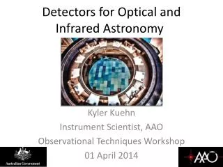
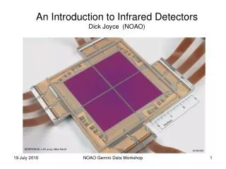
An Introduction to Infrared Detectors Dick Joyce (NOAO). NEWFIRM 4K x 4K array; Mike Merrill. Now that you know all about CCDs…. Introduction to the infrared Physics of infrared detectors Detector architecture Detector operation Observing with infrared detectors

E N D
An Introduction to Infrared Detectors Dick Joyce (NOAO) NEWFIRM 4K x 4K array; Mike Merrill NOAO Gemini Data Workshop
Now that you know all about CCDs….. • Introduction to the infrared • Physics of infrared detectors • Detector architecture • Detector operation • Observing with infrared detectors • Forget what you know about CCDs…. • Imaging and spectroscopy examples NOAO Gemini Data Workshop
Define infrared by detectors/atmosphere • “visible”: 0.3 – 1.0 μm; CCDs • Near-IR: 1.0 – 5.2 μm; InSb, H2O absorption • Mid-IR : 8 – 25 μm; Si:As, H2O absorption • Far-IR: 25 – 1000 μm; airborne, space Eric Becklin, SOFIA vis near-ir mid-ir far-ir NOAO Gemini Data Workshop
CCD, IR: physics is the same • Silicon is type IV element • Electrons shared covalently in crystalline material • Acts as insulator • But electrons can be excited to conduction band with relatively small energy (1.0 eV = 1.24 μm), depending on temperature • Internal photoelectric effect • Collect electrons, read out C. Kittel, Intro. to Solid State Physics NOAO Gemini Data Workshop
Extrinsic Photoconductor • Silicon is type IV element • Add small amount of type V (As) • Similar to H atom within Si crystal • Extra electron bound to As nucleus • Very small energy required for excitation (48 meV = 26 μm) • Sensitive through mid-IR C. Kittel, Intro. to Solid State Physics NOAO Gemini Data Workshop
Intermetallic Photoconductor • Make Si-like compound • III-V (InSb, GaAs) • II-VI (HgxCd1-xTe) • Semiconductors like Si, but with different energy gap for photoexcitation • HgCdTe 0.48 eV = 2.55 μm • InSb 0.23 eV = 5.4 μm But, can excite electrons by other means…… NOAO Gemini Data Workshop
The good, bad, and ugly • Good electrons, bad electrons • Electrons have thermal energy ~ kT, can be thermally excited into conduction band (dark current) • Solution is to operate detector at low temperature • Si CCD 0.3 – 1 μm 170 K GMOS • HgCdTe 0.8 – 2.5 μm 75 – 80 K NIFS, NICI, FLAMINGOS2 • InSb 0.8 – 5.4 μm 30 K NIRI, GNIRS, PHOENIX • Si:As 5 – 28 μm 12 K MICHELLE, TReCS • Good photons, bad photons • Only want photons coming from telescope • Eliminate thermal photons from surroundings • IR instrumentation, optics are in cold vacuum environment (subject for separate presentation) NOAO Gemini Data Workshop
IR Detectors utilize different architecture • CCDs are charge-transfer devices • Photoelectrons are collected, then read out by transfer from row to row • Attempts to make charge transfer devices from IR detector materials generally unsuccessful • Silicon technology is very mature (1000s of MY experience) • Solution is to separate photodetection and readout technologies • Hybrid array: IR detector, Si readout makes use of best of each technology • Detector and readout can be separately tested (improve yield) • Same readout can be used with different IR detector materials NOAO Gemini Data Workshop
IR detector array, Si readout separately fabricated and tested Indium bumps grown on each pixel of array and readout Two arrays are carefully aligned and pressed together – indium acts as electrical connection between detector material and readout Epoxy fill to support detector material Detector must be thinned to ~ 10 μm (backside illuminated) Too thin, detector is transparent to photons Too thick, photoelectrons recombine before making it to readout Apply antireflection coating on detector to optimize quantum efficiency (high index material) Hybrid array construction NOAO Gemini Data Workshop
Hybrid architecture -- different readout • Pixels utilize “unit cell” architecture • Separate readout amplifier for each pixel • Addressed by row, column independently • No charge transfer, no charge transfer effects (charge trails….) • Bad pixels are independent of others • Readout is nondestructive • Address row/column enable, read voltage on pixel during an integration Nondestructive readout makes it possible to read out a portion of the array or to read out the array multiple times NOAO Gemini Data Workshop
Integration defined electronically (no shutter) Initially, bias pixel to Vb Creates potential well (capacitor) Release, get jump (kTC jump) Photoelectrons accumulate After bias, sample voltage V1 After time t, sample voltage V2 Subtract two readouts—difference is the final image This technique is known as Double Correlated Sampling (DCS) Bias kTC jump is automatically removed Minimum integration time is array readout time (several seconds) Two readouts increases read noise by 1.414 Nondestructive readout is versatile time V2 V1 Vb t NOAO Gemini Data Workshop
IR arrays have higher read noise than CCD 15 – 35 e vs 4-6 e Higher capacitance Surface channel readout Al Fowler (NOAO detector engineer) utilized multiple readouts at beginning and end of readout cycle “Fowler” sampling Can reduce read noise by almost N1/2 GNIRS achieves 7 e with N=32 Other readout mode is to sample during entire integration Fit slope to samples, can achieve similar read noise reduction More applicable to space instrumentation in removing discontinuities due to particle events Nondestructive readout is versatile (2) time V2 V1 Vb t NOAO Gemini Data Workshop
The good, bad, and ugly (continued) • More bad photons come through the telescope • Sky is very bright in IR, compared to visible • Moonlight not an issue > 1 μm • OH emission lines 0.8 – 2.3 μm • Thermal emission from telescope and atmosphere • Even in K band, one wants to detect sources at 10-3 of sky (13 mag-arcsec-2) • In mid-IR, sky is brighter than 0 mag-arcsec-2 NOAO Gemini Data Workshop
So, here’s what we have to deal with.. • Raw K-band image of field shows stars, but also substantial sky signal • Sky signal intensity varies over field • Large-scale variations • Illumination • Quantum efficiency variations • Small-scale variations • Pixel-to-pixel variations • Array defects • High dark current pixels (mavericks) • These can be corrected by appropriate calibration images • Dark frames (bias) • Flatfield images NOAO Gemini Data Workshop
When we try this (CCD style)… • Obtain science images • Obtain calibration images • Dark frames at same integration time • Flatfield images of uniform target • Subtract dark frame from science images • Divide dark-subtracted images by flatfield • Image of science field with uniform sky level • Subtract (constant) sky level from image • But, here is what we get….. • Better, but still see substantial sky variations Small flatfield errors on sky still larger than faint science targets NOAO Gemini Data Workshop
Since the sky is the problem… • Subtract out the sky ( or as much as possible) before the flatfield correction • Obtain two images of field, move telescope between • Subtract two images • Eliminate almost all sky signal • Subtracts out dark current, maverick pixels • Divide by flatfield image • Result has almost no sky structure Subtracting sky minimizes effects of flatfield errors (but noise increased by 1.4) NOAO Gemini Data Workshop
Typical sequence for IR imaging • Multiple observations of science field with small telescope motions in between (dithering) • Sky background limits integration time • Moving sources samples sky on all pixels • Moving sources avoids effects of bad/noisy pixels • Combine observations using median filtering algorithm • Effectively removes stars from result sky image • Averaging reduces noise in sky image • Subtract sky frame from each science frame sky subtracted images • Divide sky subtracted images by flatfield image • Dome flat using lights on – lights off to subtract background • Sky flat using sky image – dark image using same integration time • Twilight flats – short time interval in IR • Shift and combine flatfielded images • Rejection algorithm (or median) can be used to eliminate bad pixels from final image NOAO Gemini Data Workshop
Here’s what it looks like…. Sky frame Median Subtract sky, divide each by Flatfield NOAO Gemini Data Workshop
Shift and combine images • NGC 7790, Ks filter • 3 x 3 grid • 50 arcsec dither offset Bad pixels eliminated From combined image Higher noise in corners than in center (fewer combined images) NOAO Gemini Data Workshop
This works fine in sparse fields, but what about crowded fields, extended targets? • In addition to dithered observations of science field (still necessary for sampling good pixels), it is necessary to obtain dithered observations of a nearby sparse field to generate a sky image. • Requires additional observing overhead, but this is the only way to obtain proper sky subtraction “And if you try to cheat, and don’t take the proper number of sky frames, then you get what you deserve” --Marcia Rieke NOAO Gemini Data Workshop
An example: M42 Raw image in narrowband H2 filter Off-source sky frame Sky-subtracted, flatfielded image NOAO Gemini Data Workshop
Mid-infrared strategy • Sky background at 10 μm is 103 – 104 greater than in K band • Detector wells saturate in very short time (< 50 ms) • Very small temporal variations in sky >> astronomical source intensities • Read array out very rapidly (20 ms), coadd images • Sample sky at high rate (~ 3 Hz) by chopping secondary mirror (15 arcsec) • Synchronize with detector readout, build up “target” and “sky” images • But tilting of secondary mirror introduces its own offset signal • Remove offset by nodding telescope (30 s) by amplitude of chop motion • Relative phase of target changed by 180° with respect to chop cycle • Relative phase of offset signal unchanged • Subtraction adds signal from target, subtracts offset • http://www.gemini.edu/sciops/instruments/t-recs/imaging …… chop nod NOAO Gemini Data Workshop
Spectroscopy uses similar strategy 1.89 1.42 1.13 0.94 • Example: GNIRS spectrum • R ~ 2000, cross-dispersed • 0.8 – 2.5 μm in five orders • Strong, wavelength-dependent sky • OH emission lines 0.8 – 2.3 μm • Thermal continuum 2.0 + μm • Atmospheric absorption > 2.3 μm shows up as emission in thermal • Need to subtract out sky 2.55 1.91 1.53 1.27 1.09 NOAO Gemini Data Workshop
Subtract sky by dithering along slit • First 900s exposure • Move QSO 4 arcsec along slit, expose • Subtract • Eliminates most of sky lines • OH emission time variable • Very small (.02 pixel) instrument flexure • Remove residual sky using software NOAO Gemini Data Workshop
Summary • Infrared arrays utilize same physics as CCDs • Architecture is different from CCDs • Hybrid construction: separate detector and readout • Unit cell: row/column addressing – no charge transfer • Nondestructive readout – double; multiple correlated sampling • Low temperature operation • Minimize detector dark current (bad electrons) • Minimize thermal radiation from instrument (bad photons) • More bad photons – sky is limiting factor in infrared • Imaging: sky >> astronomical signals • Spectroscopy: sky bright, emission lines • Strategy: dithering to eliminate sky contribution Review article: George Rieke 2007, Ann. Rev. Astr. Ap. 45, 77. NOAO Gemini Data Workshop
Backup NOAO Gemini Data Workshop
SOURCE OBSERVATIONS (DITHERED) SKY OBSERVATIONS (DITHERED) [MEDIAN] [MEDIAN] SKY [―] DOME FLATS ON SKY SUBTRACTED IMAGES DARKS DOME FLATS OFF [―] [―] FLAT [ / ] SKY SUBTRACTED, FLATTENED IMAGES SHIFT, ALIGN SOURCES [MEDIAN] AVERAGED IMAGE NOAO Gemini Data Workshop