Download
1 / 50
500 likes | 616 Vues
Introduction to infrared sensors. B. R. Reddy AAMU, Physics Normal, AL 35762 E-mail: brreddy@aamu.edu. June 08, 2004. Units of measurement. Photon energy= h ν = hc/ λ (where ν is the frequency) c= 3x10 8 m/s; h =6.63x10 -34 J.s If λ =500 nm

E N D
Introduction to infrared sensors B. R. Reddy AAMU, Physics Normal, AL 35762 E-mail: brreddy@aamu.edu June 08, 2004
Units of measurement • Photon energy= hν = hc/λ (where ν is the frequency) • c= 3x10⁸m/s; h =6.63x10⁻³⁴J.s • If λ=500 nm • ν =c/λ =3x10⁸m/s/500x10-9 m=6x10¹⁴Hz • Wavelength (nm, μm, Å) • 1nm = 10-9 m; 1 μm=10-6m; 1 Å=10-10m • Wavenumber(cm-1)=1/ λ =1/500nm=20 000cm-1 • 1eV = 1.6x10⁻¹⁹J • 1 eV= 8066 cm-1 • 1 cm-1 = 30 GHz • Number of photons = power/photon energy
Electromagnetic waves • wave typewavelength(m) frequency(Hz) • Gamma rays 10-11-10-17 1019-1025 • X-rays 10-9-10-12 1017-1020 • VUV 10-8-10-9 ~1017 • UV 10-7-10-8 ~1016 • Visible (0.4-0.8)10-6 ~1014 • IR 10-6-10-3 1011-1014 • Microwave 10-3-0.1 109-1011 • TV 0.3-8 ~108 • Radiowaves 10-106 107-102 • AC power 60
PMT Detectors photocathode dynodes • Photon detectors: respond to individual photons • External/Photoemissive (photomultipliers) • Internal/Photoconductive&photovoltaic (semiconducors) • Thermal detectors: respond to the heat content • Bolometers • Golay detectors • Calorimeters • Thermopyle detectors • Pyroelectric detectors • PMT : >10% quantum efficiency • operate at room temperature • Semiconductors (for IR): require cooling to cryogenic temp. • Phosphors (IR can stimulate visible Radiation) • Photographic film (UV/VIS) • Human Eye: (400-700nm) max @555nm • IRQC – No suitable materials • No commercial device yet C V semiconductor
Photon and phonon • Photon is a quantum of light • Absorption: electron goes to a higher level • Emission: electron falls down to a lower level • Obey certain selection rules • Phonon is a quantum of lattice vibration • Relaxation: radiative-- light emission :Nonradiative relaxation-- no light emission • Nonradiative: gases: collisional relaxation • Solids: Multiphonon relaxation
Performance Parameters • Spectral response = wavelength interval measured • Responsivity = electrical output/power • Noise Equivalent Power (NEP) • Detectivity (D*)= √area/NEP(λ, 1Hz, T) (cm √Hz/watt) • D* indicates the wavelength at which it was measured, the chopping frequency and the noise bandwidth. • Signal/noise ratio ( 3 or higher) • Response time: How fast does it respond • Quantum efficiency= #electrons/#photons < 1 • NEP: is the incident light level impinging on a diode which produces photocurrent equal to the noise level. • Function of detector responsivity, noise (of the detector & circuitry) and frequency bandwidth over which the noise is measured.
Transmission of detector windows • Quartz: 180 nm – • Glass: 360nm – 3 μm • Fluorite: 125nm – 9 μm • ZnSe: 550nm – 16 μm • Si: 1.1 – 9 μm 22 – 50 μm detector window
Relative response #Photons = Power/photon energy = P/hν = Pλ/hc • Unit power at all wavelengths Photon detector Relative output (a.u.) Thermal detector Wavelength
Johnson noise (Thermal noise) • Due to random motion of electrons in resistive elements (thermal agitation) • Increases with temperature • Occurs at all frequencies (white noise) • Noise voltage depends on the frequency bandwidth of the system • Vrms = √(4kTRΔf) • Noise is eliminated at 0K Noise power density White noise f
Shot noise • Due to random movement of discrete charges across a junction (pn-junction) • Electrons are released at random times (photo tube) • broadband (expressed as noise per unit bandwidth) • statistical noise associated with photocurrent and dark current • Irms = √(ei/t) = √(2eiΔf)
1/f noise Source not known Decreses at high frequencies Significant at <100Hz Interference noise Other noise sources Noise Power density 120 180 240 60 f Noise Power density Note: acquire data above kHz to minimize f
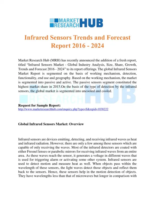
Why infrared detectors? • Infrared: near-infrared (700 nm to 2 microns) • Mid-infrared region (2 to 5 microns) • LW infrared (above 6 microns) • Clouds absorb visible light • Atmospheric gases absorb certain wavelengths • Atmospheric windows • Mid-infrared region (2 to 5 microns) • Longwave infrared region (~ 10 microns) • Useful for space communications • So a detector is needed
IR detector applications • Military • Industrial process control • Security systems • Medical applications • Astronomy • Thermal imaging and pollution control • Cover a wide range: 0.8 to 100 microns)
Photon detectors What is the limitation of existing detectors? PMT semiconductor There is a need for alternate schemes for IR region
Why to cool a detector? • To minimize thermal noise Bandgap energy ΔE=Eg=Ec-Ev Incident photon energy >bandgap energy hν >Eg Ec IR detectors: small bandgap noise (thermal contribution) Ev Ex: HgCdTe, ΔE=0.1eV Say there are 1000 electrons N= Nc+Nv=1000 Nc/Nv = e-806.6/204=0.019=1.9% a large fraction (NEP is high) So cool it to minimize noise T=77K Nc/Nv=e-806.6/53.5=3x10-7=3x10-5% Nc is negligible Nc = Nve-ΔE/kT Ni population in the ith band (i= v or c) K Boltzmann constant=1.38x10⁻²³J/K T absolute temperature N=1000 & Nc=0.019Nv Nc+Nv=0.019Nv+Nv=1000 Nv=1000/1.019=981 Nc=19
Bandgaps and operating temperatures • Material bandgap (eV) λcutoff(μm) temp.(K) • Si 1.12 1.1 295 • Ge 0.67 1.8 295 • CdTe 1.5 0.83 295 • PbS 0.42 2.9 295 • InSb 0.23 5.4 77 • HgCdTe 0.1 12 77 • λcutoff(μm) is the longest wavelength that can be detected • For detection: hν≥Eg • λcutoff(μm)= hc/Eg = 6.63x10-34x3x108 J.m/Eg • =1.24/Eg (where Eg is in eV)
Infrared detection • Thermal detection • Photon detectors • IRQC • MIRROR (uses bimaterial cantilevers) • Microoptomechanical infrared receiver with optical readout (MIRROR)-optomechanical • Ex: SiN/Au • Au: large thermal expansion coeficient~1.4x10⁻⁵/K • Thermal conductivity ~296 watt/meter.Kelvin • SiN:smallthermal expansion coefficient ~8x10⁻⁷/K • Thermal conductivity ~3 watts/meter.Kelvin • Absorbs IR (8-14 μm)
Thermal detectors • Bolometer: temperature changes when exposed to radiation, causing a proportionate change in resistance. • Thermopile: a number of thermocouples are connected in series. • A minimum of two junctions (one at a higher temp. the other at a lower temp.). • a junction is made of two different materials. • Pyroelectric detectors:use ferroelectric crystals (chopper) • Possess permanent dipole moment below curie temp. • Heat changes lattice distance & hence polarization changes • Polarization change also changes the capacitance • So current or voltage changes
Thermal detectors • Golay detectors: Heat causes a change in pressure. A thin film absorbs incident radiation & the enclosed gas is heated. • A tube connects heated cell to another cell that has a flexible film. This film is distorted by a pressure change in the other. This film acts as a (light) deflecting mirror. • Very slow • Slow response • Useful to detect Visible to mm wavelengths 1010 light Response (a.u.) D* 108 Flexible film wavelength 1 100 Pressure cell Chop freq
Thermal detectors • Thermocouple:junction of two different metals • Work function is different. A current is generated when heated. Requires a reference. Produces (μV/°C) • Thermopile: several thermocouples connected in series • Pyroelectric detectors: electric polarization changes with temperature, resulting in a detectable current hot cold
Pyroelectric detectors • Uses temperature sensitive ferroelectric crystals (TGS, SBN, LiNbO3, Lithium tantalate) • Electrodes are attached to the crystals • Spontaneous polarization can be measured as a voltage • Contant T: internal charge distribution is neutralized by free electrons and surface charges. So no voltage is detected. • If the temperature changes, the lattice distance & polarization changes, producing transient voltage • Modulate the radiation: detector temperature alternates • Below curie temp.: individual dipoles align (net internal field) • Heat (radiation) disrupts the alignment and charge distribution on the faces and hence the stored charge on the electrodes • Measure: change in the stored charge (chopper is used) • Current, I =pA (d ΔT/dt) where p is the pyroelectric coefficient
Calorimeter • Some models are water cooled • Difference in inlet and outlet temperature is used to estimate energy absorbed • Power absorbed, P = dQ/dt = c ΔTdm/dt C = specific heat capacity ΔT = change in temperature dm/dt = rate of mass flow
Calorimeter • Design • Al/Cu alloy coated with black paint (embedded with thermocouples) • Absorbed radiation increases temperature (sensed by embedded thermocouples) • Thermal inertia is inherent (heat conduction is involved) • Its response is very slow • Useful for the detection of very high powers • Useful from UV to far IR Water in Power absorbed P = dQ/dt = c ΔTdm/dt dm/dt mass flow rate ΔT temperature change C heat absorbed Water out
Phosphors • IR stimulates emission of visible radiation • These phosphors have been previously excited by UV radiation • Ex: ZnS: stimulated by IR (1 to 3 microns) • Rare-earth doped phosphors convert near-IR to visible
MIcrobolometer • Thermal imaging: 8 -12 microns or 3 -5 microns • At 25°C an object emits 50x more radiation at 8- 12 micron band than at 3 -5 micron band • Thermal detectors (bolometers): measure the total energy absorbed by a change in the temperature of the detector elements • Principle: electrical resistance varies with temperature • Note: If an absorber is thermally isolated- any increase in absorbed radiation produces increase in emitted radiation
Microbolometer • Individual elements are suspended by electrical conductors • Measure change in resistance: determine the temperature change and IR input • Intensity of 1mW/cm2 increases temperature by 1K. • Slow response: device has to absorb enough heat to reach equilibrium before an accurate measurement could be made • Solution: miniaturization (response time is proportional to thickness of the absorber) • 0.5 microns, response time of ~10 ms
Microbolometer (good for RT, but slow) • Materials: Si, barium strontium titanium oxide, vanadium oxide • Must have large temperature coefficient of resistance; TCR = (ΔR/R)/ΔT • Detect temp. changes of 0.07K • Response (10mV/K) • Polycrystalline silicon-germanium • Performance limit: heat is almost lost by radiation conductors Bolometer material
Absorption and emission When the incident radiation energy equals the energy level gap then it is absorbed, otherwise it is transmitted through the sample. Whenever an electron jumps to a lower level the difference in energy comes out as light Absorption and emission have to obey selection rules Atoms are stable in the ground state. Excited atoms relax to the lower levels Allowed transitions: lifetimes are ~ ns Forbidden transitions: lifetimes ~ms to μs τ
Micro-optomechanical device • Principle:absorption of IR raises the temp. The material is distorted. Deflection of a VIS beam is monitored • SiN/Au material Visible reflector (Au) IR absorber (SiN) Mat. Ther.cond. Exp.coef. Heat cap. SiN 3 0.8x10⁻⁶ 691 Au 296 14.2 129
Electron orbits Energy levels Atomic energy levels e N Intensity (a.u.) frequency
Infrared Quantum counter detection concept: Nobel Laureate Nicholas Bloembergen • What is it? • Infrared-optical double resonance IR Uv-vis IR VIS Uv-vis Uv-vis IR vis vis IR IR Ionic energy levels Ionic energy levels Ionic energy levels
4S3/2 5S2 4F9/2 5F5 4I9/2 5I8 IRQC schemes in different systems
Fig. (a) Ar+ excitation (b) Ar+ and Ti:Sapphire Sample:LaF3:Tb3+
Cut-off phonon LaF3: ~350 cm-1 LaCl3: ~260cm-1 LaBr3: ~175cm-1 Note: Material selection is important
STEP ETU AVALANCE ABS. t t t
IR to Visible upconversion studies • Sequential two/three photon excitation (single ion process) • Energy transfer upconversion (two/three ions) • Avalanche absorption (two ions) IR VIS
4I9/24I15/2 4S3/24I15/2 Composition La2O3(2.3%) PbO(13.7%) TeO2(28.7%) MgTiO3(6.4%) SiO2(25.4%) B2O3(21.9%) Ba3Y3WO9(1.6%) 4S3/24I13/2 Er3+ -doped glass (A.P.L.)
O O Ion(1) Ion(2)
Why doped fiber? Draw backs of crystal: Small interaction length (~1 cm) Beam size is large 30 microns Most of the incident light is wasted A small fraction of the light is collected small solid angle crystal Fiber vs. crystal Light in output fiber Advantages of fiber: Small fiber core (~2 – 5 microns) long interaction length at least 50% of emitted light comes out
Energy levels of Er3+ in LaF3 (J.A.P.)
ZBLAN fiber ZrF4(53% ) BaF2(20% ) LaF3(3.9%) AlF3(3%) NaF(20%) violet blue green Er3+ in fluoride fiber (OL)
Dichroic mirror for coupling and launching light into fiber • Light coupling
IRQC studies in Eu3+ doped materials (JOSA-B)