Download
1 / 57
570 likes | 791 Vues
Introduction to infrared detection and temperature sensing. B. Rami Reddy AAMU, Physics Normal, AL 35762 E-mail: rami.bommareddi@aamu.edu NSF RISE Workshop/Short Course. July 12, 2007. Units of measurement. Photon energy= hf = hc/ λ (where f is the frequency)

E N D
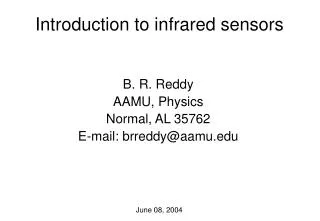
Introduction to infrared detection and temperature sensing B. Rami Reddy AAMU, Physics Normal, AL 35762 E-mail: rami.bommareddi@aamu.edu NSF RISE Workshop/Short Course July 12, 2007
Units of measurement • Photon energy= hf = hc/λ (where f is the frequency) • c= 3x10⁸m/s; h =6.63x10⁻³⁴J.s • If λ=500 nm • f =c/λ =3x10⁸m/s/500x10-9 m=6x10¹⁴Hz • Wavelength (nm, μm, Å) • 1nm = 10-9 m; 1 μm=10-6m; 1 Å=10-10m • Wavenumber(cm-1)=1/ λ =1/500nm=20 000cm-1 • 1eV = 1.6x10⁻¹⁹J • 1 eV= 8066 cm-1 • 1 cm-1 = 30 GHz • Number of photons = power/photon energy
Electromagnetic waves • wave typewavelength(m) frequency(Hz) • Gamma rays 10-11-10-17 1019-1025 • X-rays 10-9-10-12 1017-1020 • VUV 10-8-10-9 ~1017 • UV 10-7-10-8 ~1016 • Visible (0.4-0.7)10-6 ~1014 • IR 10-6-10-3 1011-1014 • Microwave 10-3-0.1 109-1011 • TV 0.3-8 ~108 • Radiowaves 10-106 107-102 • AC power 60
PMT Detectors photocathode dynodes • Photon detectors: respond to individual photons • External/Photoemissive (photomultipliers) • Internal/Photoconductive&photovoltaic (semiconducors) • Thermal detectors: respond to the heat content • Bolometers • Golay detectors • Calorimeters • Thermopyle detectors • Pyroelectric detectors • PMT : >10% quantum efficiency • operate at room temperature • Semiconductors (for IR): require cooling to cryogenic temp. • Phosphors (IR can stimulate visible Radiation) • Photographic film (UV/VIS) • Human Eye: (400-700nm) max @555nm • IRQC– No suitable materials • No commercial device yet C V semiconductor
Photon and phonon ● • Photon is a quantum of light • Absorption: electron goes to a higher level • Emission: electron falls down to a lower level • Obey certain selection rules • Phonon is a quantum of lattice vibration • Relaxation: radiative-- light emission :Nonradiative relaxation-- no light emission • Nonradiative: - gases: collisional relaxation • Solids: Multiphonon relaxation ●
Performance Parameters • Spectral response = wavelength interval measured • Responsivity = electrical output/power • Noise Equivalent Power (NEP) • Detectivity (D*)= √area.Δf/NEP(λ, 1Hz, T) (cm √Hz/watt) • D* indicates the wavelength at which it was measured, the chopping frequency and the noise bandwidth. • Signal/noise ratio ( 3 or higher) • Response time: How fast does it respond • Quantum efficiency= #electrons/#photons < 1 • NEP: is the incident light level impinging on a diode which produces photocurrent equal to the noise level. • Function of detector responsivity, noise (of the detector & circuitry) and frequency bandwidth over which the noise is measured.
Transmission of detector windows • Quartz: 180 nm – • Glass: 360nm – 3 μm • Fluorite: 125nm – 9 μm • ZnSe: 550nm – 16 μm • Si: 1.1 – 9 μm 22 – 50 μm detector window
Relative response #Photons = Power/photon energy = P/hν = Pλ/hc • Unit power at all wavelengths Photon detector Relative output (a.u.) Thermal detector Wavelength
Johnson noise (Thermal noise) • Due to random motion of electrons in resistive elements (thermal agitation) • Increases with temperature • Occurs at all frequencies (white noise) • Noise voltage depends on the frequency bandwidth of the system • Vrms = √(4kTRΔf) • Noise is eliminated at 0K Noise power density White noise f
Shot noise • Due to random movement of discrete charges across a junction (pn-junction) • Electrons are released at random times (photo tube) • broadband (expressed as noise per unit bandwidth) • statistical noise associated with photocurrent and dark current • Irms = √(ei/t) = √(2eiΔf)
1/f noise Source not known Decreses at high frequencies Significant at <100Hz Interference noise Other noise sources Noise Power density 120 180 240 60 f Noise Power density Note: acquire data above kHz to minimize f
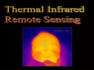
Why infrared detectors? • Infrared: • near-infrared (700 nm to 2 microns) • Mid-infrared region (2 to 5 microns) • LW infrared (above 6 microns) • Clouds absorb visible light • Atmospheric gases absorb certain wavelengths • Atmospheric windows • Mid-infrared region (2 to 5 microns) • Longwave infrared region (~ 10 microns) • Useful for space communications • So a RT IR detector is needed
IR detector applications • Military • Industrial process control • Security systems • Medical applications • Astronomy • Thermal imaging and pollution control • Cover a wide range: 0.8 to 100 microns)
Photon detectors What are the limitations of existing detectors? PMT semiconductor Note: Noise due to thermalization is large at RT There is a need for alternate schemes for IR region
Why to cool a detector? • To minimize thermal noise Bandgap energy ΔE=Eg=Ec-Ev Incident photon energy >bandgap energy hν >Eg Ec IR detectors: small bandgap noise (thermal contribution) Ev Ex: HgCdTe, ΔE=0.1eV Say there are 1000 electrons N= Nc+Nv=1000 Nc/Nv = e-806.6/204=0.019=1.9% a large fraction (NEP is high) So cool it to minimize noise T=77K Nc/Nv=e-806.6/53.5=3x10-7=3x10-5% Nc is negligible Nc = Nve-ΔE/kT Ni population in the ith band (i= v or c) K Boltzmann constant=1.38x10⁻²³J/K T absolute temperature N=1000 & Nc=0.019Nv Nc+Nv=0.019Nv+Nv=1000 Nv=1000/1.019=981 Nc=19
Bandgaps and operating temperatures • Material bandgap (eV) λcutoff(μm) temp.(K) • Si 1.12 1.1 295 • Ge 0.67 1.8 295 • CdTe 1.5 0.83 295 • PbS 0.42 2.9 295 • InSb 0.23 5.4 77 • HgCdTe 0.1 12 77 • λcutoff(μm) is the longest wavelength that can be detected • For detection: hν≥Eg • λcutoff(μm)= hc/Eg = 6.63x10-34x3x108 J.m/Eg • =1.24/Eg (where Eg is in eV)
Infrared detection • Thermal detection • Photon detectors • IRQC • MIRROR (uses bimaterial cantilevers) • Microoptomechanical infrared receiver with optical readout (MIRROR)-optomechanical • Ex: SiN/Au • Au: large thermal expansion coeficient~1.4x10⁻⁵/K • Thermal conductivity ~296 watt/meter.Kelvin • SiN:smallthermal expansion coefficient ~8x10⁻⁷/K • Thermal conductivity ~3 watts/meter.Kelvin • Absorbs IR (8-14 μm)
Thermal detectors • Bolometer: temperature changes when exposed to radiation, causing a proportionate change in resistance. • Thermopile: a number of thermocouples are connected in series. • A minimum of two junctions (one at a higher temp. the other at a lower temp.). • a junction is made of two different materials. • Pyroelectric detectors:use ferroelectric crystals (chopper) • Possess permanent dipole moment below curie temp. • Heat changes lattice distance & hence polarization changes • Polarization change also changes the capacitance • So current or voltage changes
Thermal detectors • Golay detectors: Heat causes a change in pressure. A thin film absorbs incident radiation & the enclosed gas is heated. • A tube connects heated cell to another cell that has a flexible film. This film is distorted by a pressure change in the other. This film acts as a (light) deflecting mirror. • Very slow • Slow response • Useful to detect Visible to mm wavelengths 1010 light Response (a.u.) D* 108 Flexible film wavelength 1 100 Pressure cell Chop freq
Thermal detectors • Thermocouple:junction of two different metals • Work function is different. A current is generated when heated. Requires a reference. Produces (μV/°C) • Thermopile: several thermocouples connected in series • Pyroelectric detectors: electric polarization changes with temperature, resulting in a detectable current hot cold
Pyroelectric detectors • Uses temperature sensitive ferroelectric crystals (TGS, SBN, LiNbO3, Lithium tantalate) • Electrodes are attached to the crystals • Spontaneous polarization can be measured as a voltage • Constant T: internal charge distribution is neutralized by free electrons and surface charges. So no voltage is detected. • If the temperature changes, the lattice distance & polarization changes, producing transient voltage • Modulate the radiation: detector temperature alternates • Below curie temp.: individual dipoles align (net internal field) • Heat (radiation) disrupts the alignment and charge distribution on the faces and hence the stored charge on the electrodes • Measure: change in the stored charge (chopper is used) • Current, I =pA (d ΔT/dt) where p is the pyroelectric coefficient
Calorimeter • Some models are water cooled • Difference in inlet and outlet temperature is used to estimate energy absorbed • Power absorbed, P = dQ/dt = c ΔTdm/dt C = specific heat capacity ΔT = change in temperature dm/dt = rate of mass flow
Calorimeter • Design • Al/Cu alloy coated with black paint (embedded with thermocouples) • Absorbed radiation increases temperature (sensed by embedded thermocouples) • Thermal inertia is inherent (heat conduction is involved) • Its response is very slow • Useful for the detection of very high powers • Useful from UV to far IR Water in Power absorbed P = dQ/dt = c ΔTdm/dt dm/dt mass flow rate ΔT temperature change C heat absorbed Water out
Phosphors • IR stimulates emission of visible radiation • These phosphors have been previously excited by UV radiation • Ex: ZnS: stimulated by IR (1 to 3 microns) • Rare-earth doped phosphors convert near-IR to visible
MIcrobolometer • Thermal imaging: 8 -12 microns or 3 -5 microns • At 25°C an object emits 50x more radiation at 8- 12 micron band than at 3 -5 micron band • Thermal detectors (bolometers): measure the total energy absorbed by a change in the temperature of the detector elements • Principle: electrical resistance varies with temperature • Note: If an absorber is thermally isolated- any increase in absorbed radiation produces increase in emitted radiation
Microbolometer • Individual elements are suspended by electrical conductors • Measure change in resistance: determine the temperature change and IR input • Intensity of 1mW/cm2 increases temperature by 1K. • Slow response: device has to absorb enough heat to reach equilibrium before an accurate measurement could be made • Solution: miniaturization (response time is proportional to thickness of the absorber) • 0.5 microns, response time of ~10 ms
Microbolometer (good for RT, but slow) • Materials: Si, barium strontium titanium oxide, vanadium oxide • Must have large temperature coefficient of resistance; TCR = (ΔR/R)/ΔT • Detect temp. changes of 0.07K • Response (10mV/K) • Polycrystalline silicon-germanium • Performance limit: heat is almost lost by radiation conductors Bolometer material
Micro-optomechanical device • Principle:absorption of IR raises the temp. The material is distorted. Deflection of a VIS beam is monitored • SiN/Au material Visible reflector (Au) IR absorber (SiN) Mat. Ther.cond. Exp.coef. Heat cap. SiN 3 0.8x10⁻⁶ 691 Au 296 14.2 129
IRQC Materials
absorption emission Asorption and emission ◦ ◦ hf hf ● ● ● ● Emitted wavelength depends on the energy gap hf
IR to Visible upconversion studies • Sequential two/three photon excitation (single ion process) • Energy transfer upconversion (two/three ions) • Avalanche absorption (two ions) IR VIS IRQC
Energy levels of Er3+ in LaF3 (J.A.P.)
ZBLAN fiber ZrF4(53% ) BaF2(20% ) LaF3(3.9%) AlF3(3%) NaF(20%) violet blue green Er3+ in fluoride fiber (OL)
Infrared Quantum counter detectionconcept: Nobel Laureate Nicholas Bloembergen • What is it? • Infrared-optical double resonance IR Uv-vis IR VIS Uv-vis Uv-vis IR vis vis IR IR Ionic energy levels Ionic energy levels Ionic energy levels
4S3/2 5S2 4F9/2 5F5 4I9/2 5I8 IRQC schemes in different systems
uv IRQC scheme in Tm3+ doped system
IRQC studies in Eu3+ doped materials (JOSA-B)
Fig. (a) Ar+ excitation (b) Ar+ and Ti:Sapphire Sample:LaF3:Tb3+
Why doped fiber? Draw backs of crystal: Small interaction length (~1 cm) Beam size is large 30 microns Most of the incident light is wasted A small fraction of the light is collected small solid angle crystal Fiber vs. crystal Light in output fiber Advantages of fiber: Small fiber core (~2 – 5 microns) long interaction length at least 50% of emitted light comes out
Dichroic mirror for coupling/launching light into fiber • Light coupling
Temperature measurement • Relaxation • Radiative • Non-radiative (exhibits temperature dependence) • Multi-phonon relaxation • Ion-ion coupling/energy transfer interaction • Non-radiative relaxation • Energy-gap between the excited level • Cut-off phonon frequency • Reduced mass of the sample • Force constant • Ex: LaBr3 (175 cm-1), LaCl3 (260 cm-1), LaF3 (350 cm-1)
Why Temperature Dependence? • Phonon-assisted radiative transitions • Single and multiphonon nonradiative decay • Thermal population of nearby levels which have different decay rates • Increased or decreased radiation trapping caused by changes in the absorption or emission line shapes • Similarly ion-ion coupling (energy transfer rate) is also affected.
W(T) = W(0) [1+m]n Where m is the phonon density n is the number of phonons involved (n = energy gap/phonon energy) W(0) = c exp(αΔE) Relaxation pathways