Download
1 / 35
360 likes | 546 Vues
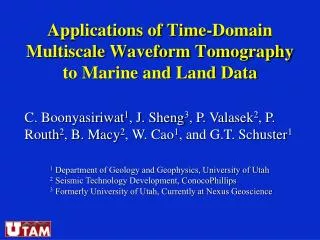
Applications of Time-Domain Multiscale Waveform Tomography to Marine and Land Data. C. Boonyasiriwat 1 , J. Sheng 3 , P. Valasek 2 , P. Routh 2 , B. Macy 2 , W. Cao 1 , and G.T. Schuster 1. 1 Department of Geology and Geophysics, University of Utah

E N D
Applications of Time-DomainMultiscale Waveform Tomographyto Marine and Land Data C. Boonyasiriwat1, J. Sheng3, P. Valasek2, P. Routh2, B. Macy2, W. Cao1, and G.T. Schuster1 1 Department of Geology and Geophysics, University of Utah 2 Seismic Technology Development, ConocoPhillips 3 Formerly University of Utah, Currently at Nexus Geoscience
Outline • Introduction • Time-domain multiscale waveform tomography • Processing workflow • Field data results: • Gulf of Mexico • Saudi Arabia • Summary 1
Waveform Tomography True Vp Velocity of Marmousi II Model 0 0 4500 4500 Depth (km) Depth (km) 4 4 1000 1000 Reconstructed Vp Velocity Model 0 Horizontal Position (km) 16 • Wave-equation based model building technique. Boonyasiriwat et al., 2008 2
Problem and Solution Problem: Find a velocity model from seismic data that minimizes the data residual Proposed Solution: - Use a gradient-based method - Use a multiscale method in X-T domain 3
Initial Velocity Calculated Wavefield Wavefield Residual Velocity Update Iterate until wavefield residual is small Waveform Tomography True Velocity Observed Wavefield 4
Outline • Introduction • Time-domain multiscale waveform tomography • Processing workflow • Field data results: • Gulf of Mexico • Saudi Arabia • Summary 5
Why Use Multiscale? Misfit function ( f ) Model parameter (m) Low Frequency Coarse Scale High Frequency Fine Scale Image from Bunks et al. (1995) 6
syn. 2. Generate synthetic data d(x,t) by FD method syn. 2 3. Adjust v(x,z) until ||d(x,t)-d(x,t) || minimized by CG. mute b). Use multiscale: low freq. high freq. Multiscale Waveform Tomography 1. Collect data d(x,t) 4. To prevent getting stuck in local minima: a). Invert early arrivals initially 7
Outline • Introduction • Time-domain multiscale waveform tomography • Processing workflow • Field data results: • Gulf of Mexico • Saudi Arabia • Summary 8
Estimating Source Wavelet Generating Initial Model Multiscale Waveform Tomography Validating Velocity Tomograms Processing Workflow Pre-Processing of Data 9
Estimating Source Wavelet Generating Initial Model Multiscale Waveform Tomography Validating Velocity Tomograms Processing Workflow Pre-Processing of Data 3D-to-2D conversion Attenuation compensation Random noise removal 9
Generating Initial Model Multiscale Waveform Tomography Validating Velocity Tomograms Processing Workflow Pre-Processing of Data Generate a stacked section Estimating Source Wavelet Pick the water-bottom Stack along the water-bottom 9
Estimating Source Wavelet Multiscale Waveform Tomography Validating Velocity Tomograms Processing Workflow Pre-Processing of Data Traveltime picking Initial model: RMS velocity Generating Initial Model Refraction traveltime inversion 9
Estimating Source Wavelet Generating Initial Model Validating Velocity Tomograms Processing Workflow Pre-Processing of Data Low-pass filtering Multiscale Waveform Tomography Inversion from low- to high-frequency bands 9
Estimating Source Wavelet Generating Initial Model Multiscale Waveform Tomography Processing Workflow Pre-Processing of Data Migration images Validating Velocity Tomograms Common image gathers 9
Outline • Introduction • Time-domain multiscale waveform tomography • Processing workflow • Field data results: • Gulf of Mexico • Saudi Arabia • Summary 10
Gulf of Mexico Data 480 Hydrophones 515 Shots dt = 2 ms Tmax = 10 s 12.5 m 11
Reconstructed Velocity Velocity (m/s) Velocity (m/s) 13
Comparing CIGs CIG from Waveform Tomogram CIG from Traveltime Tomogram 16
Comparing CIGs CIG from Waveform Tomogram CIG from Traveltime Tomogram 18
Comparing CIGs CIG from Waveform Tomogram CIG from Traveltime Tomogram 20
Outline • Introduction • Time-domain multiscale waveform tomography • Processing workflow • Field data results: • Gulf of Mexico • Saudi Arabia • Summary 21
0 5500 Depth (km) 330 1 (m/s) 0 X-Coord. (km) 45 1.6 km 100 m Y-Coord. (km) 0 km 0 0 50 X-Coord. (km) Time (s) 2 Offset (km) -3.6 3.6 Saudi Arabia Land Survey 1. 1279 CSGs, 240 traces/gather 2. 30 m station interval, max. offset = 3.6km 3. Line Length = 46 km 4. Pick 246,000 traveltimes 5. Traveltime tomography -> V(x,y,z) 22
Brute Stack Section 0 Time (s) 2.0 3920 CDP 5070 23
Traveltime Tomostatics + Stacking 0 Time (s) 2.0 3920 CDP 5070 24
Waveform Tomostatics + Stacking 0 Time (s) 2.0 3920 CDP 5070 25
Outline • Introduction • Time-domain multiscale waveform tomography • Processing workflow • Field data results: • Gulf of Mexico • Saudi Arabia • Summary 26
Summary Acoustic waveform inversion was successfully applied to both marine and land datasets, and can provide accurate velocity subsurface structures. • Issues: • Cost > 100 iterations: How to reduce cost? • Acoustic vs. Elastic: How far can we go with acoustic? • Anisotropy needed? • Source wavelet important: Source-independent inversion. • Missing low frequencies: Better initial model via reflection tomography. 27
Acknowledgment • We would like to thank • UTAM sponsors for financial support. • Amarada Hess and Saudi Aramco for providing us the datasets. 28