Mechanical Design Guidelines
Mechanical Design Guidelines. Ballooning Unit, Lecture 1. Mechanical Design Topics. How to produce mechanical drawings What mechanical interfaces do you need to specify How do material choices affect your payload What are the steps for producing a sound mechanical design

Mechanical Design Guidelines
E N D
Presentation Transcript
Mechanical Design Guidelines Ballooning Unit, Lecture 1 Mechanical Design Guidelines
Mechanical Design Topics • How to produce mechanical drawings • What mechanical interfaces do you need to specify • How do material choices affect your payload • What are the steps for producing a sound mechanical design • What should your testing procedure be • Handy, pocket size reference book is “Pocket Ref” by Thomas J. Glover available at ACE Hardware stores. Mechanical Design Guidelines
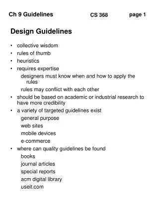
Reasons for Producing Drawings • Aide to configuration planning • Help determine what components are needed • Determine how components will go together • Check that dimensions & locations are consistent • Specify what is to be built • Proper drawings are needed by shop personnel • Communicate with management & reviewers • Document what has been built • Track changes in the configuration • Provide record of experiment configuration Mechanical Design Guidelines
Sample Drawing Mechanical Design Guidelines
Basic Views in a Drawing • Most drawings provide Top, Front and Side views • What the component would look like if viewed from that direction • Views arranged usually as if object were unfolded • Sometimes an isometric (3D) view is provided Mechanical Design Guidelines
Drawing Label • The label provides all of the information necessary to interpret the drawing and track revisions • Included in the label should be a drawing number, title, author, date, revision number, sheet number, scale, units, tolerance, material and a description of any other relevant information Mechanical Design Guidelines
Representing Hidden Surfaces • Surfaces that can be seen in a particular view are indicated by a solid line • Surfaces that are “hidden” are indicated by a dashed line • Through holes are solid circles face on and dashed for side view • Threaded holes have perpendicular dashing to indicate screw threads Mechanical Design Guidelines
Putting Dimensions on the Drawing • All surfaces, holes & cuts should be dimensioned to specify location, width, length & depth • Consistent with units and tolerance specified in label • Reference to common surface or point • Holes are specified with a radius for clearance • Threaded holes are specified with a screw size & depth • Callout boxes provide addition information Mechanical Design Guidelines
Mechanical Interfaces • There are multiple interfaces that you will need to identify, specify and control • Component to component interfaces • Where and how does each part of your experiment contact another part? • Electrical connectors, motors, actuators, hinges • Component to payload structure interfaces • Where and how do you secure your experiment components within the payload box? • Payload to balloon vehicle interface • Interface already specified in Lecture 2 • How will you implement this interface? • Your documentation should list all your interfaces and specify how they will be implemented and controlled Mechanical Design Guidelines
Material Considerations • When you choose materials for your payload you need to consider how they will affect your payload • How will a material affect your sensors? • Iron / steel will distort the readings of a magnetic sensor • Will your observation port window transmit the desired frequencies? • Will the material outgas and affect the sensor readings? • How will a material be affected by the environment? • The intense cold can embrittle many plastics and glues • Non-rigid, closed cell foam will expand dramatically in vacuum • How much does a material weigh? Is there a lighter material that will do the same job? • When in doubt obtain a material sample and test it. Mechanical Design Guidelines
Weight Budget • Early on in your project establish a weight budget • List of ALL payload parts, their weight, a weight uncertainty, the weight total and the uncertainty in this total • Weights can be estimated, calculated or measured • Large uncertainty for estimated, smaller uncertainty for measured • Initially keep a contingency of ~20% to cover missing items and weight uncertainty • The more complete (number of items, measurements instead of estimates) your weight budget is, the lower the contingency needed • As your design matures your weight budget should include more details, more measured components, lower uncertainty and lower contingency Mechanical Design Guidelines
Payload Design Questions 1 • Component Layout: • How many components does your experiment have? • Where do these components need to be located? • Component Access: • What components need to be frequently accessed (e.g. on/off switch)? • What components need to be infrequently accessed (e.g. configuration DIP switches)? • If a component needs to be replaced how will this be done? • Component Mounting: • Are there any critical alignment issues with sensors? • How will components be secured to not come loose during flight? Mechanical Design Guidelines
Payload Design Questions 2 • Payload Integration: • In what order are components assembled to produce the completed payload? • Thermal Control: • What payload surface treatments are necessary to control thermal properties? • How much insulation of what type located where is necessary to protect critical components? • Are any heaters needed? • Strength: • How will you determine that your structure is strong enough to survive the balloon flight without falling apart? Mechanical Design Guidelines
Develop a Testing Plan • Many design issues can be quantified by testing under controlled conditions • Such a Test Plan needs to address the following issues: • What components or systems need to be tested? • What test data needs to be collected? • What tests need to be performed? • What is the test procedure? • How will the data be recorded, analyzed and documented? • Need to assure payload will survive the flight environment • Thermal testing for the extremes of hot and cold • Vacuum testing for the low pressure at high altitude • Shock testing for when balloon bursts and payload lands Mechanical Design Guidelines
Major Tests • Develop prototypes or mock-ups • Test component layout and mounting • Develop specifications for mechanical interfaces • Thermal, vacuum and shock testing for strength • Thermal testing using dry ice • Tropopause temperature get down to ~-60o C and dry ice surface temperature is –78.5o C • Test glues and other materials for embrittlement • Test thermal insulation properties • A small vacuum bell jar can simulate the pressure environment • Material outgassing, expansion, high voltage corona / arcing, etc. • Major shock is on landing • Nominal decent rate is 20 fps, so drop test article about 10 feet Mechanical Design Guidelines
References • “Pocket Ref” by Thomas J. Glover, 3rd Edition, 2003, Sequoia Publishing, Inc. P.O. Box 620820, Dept. 101, Littleton, CO 80162-0820, http://www.sequoiapublishing.com/ , also available in ACE hardware stores Mechanical Design Guidelines