Design Guidelines
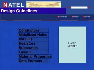
Design Guidelines. PHOTO NEEDED. Conductors Metallized Holes Via Fills Resistors Substrates Layout Material Properties Data Formats. Conductors. Minimum line width small as 2 microns for specials Minimum space width 0.0005" Standard as small as 2 microns for specials

Design Guidelines
E N D
Presentation Transcript
Design Guidelines PHOTO NEEDED Conductors Metallized Holes Via Fills Resistors Substrates Layout Material Properties Data Formats
Conductors Minimum line width small as 2 microns for specials Minimum space width 0.0005" Standard as small as 2 microns for specials Line & space tolerance 0.0001" (Ion-milled)
Metallized Holes Minimum aspect ratio 1:1, 1:2 for specials Minimum separation from edge Thickness of substrate Minimum tolerance +/- 0.001" Minimum location tolerance +/-0.0005" Minimum pad size around via 0.015" + via diameter
Resistors Minimum conductor overlap 0.002" Minimum Spacing between resistors 0.005" Minimum Pad size 0.005"
Resistor Types Text Needed Here
Resistor Trimming We use low power yag trimmers that are capable of active and passive trim. Resistor trim ranges of 1 Milliohm to 1 Gigohm are possible with an astonishing accuracy of ± .05%. We have years of experience in trimming resistors. Complete read and write systems that monitor our accuracy, percent yield, and final trim values. Electronic data transfer of resistor values can be provided for your convenience. For circuit trimming, circuit performance adjustments are accomplished via resistor values per individual circuit. Thin Film Resistor TrimmingTight tolerances is a critical requirement in thin film contract trimming services. P/M Industries is capable of trimming to tight tolerances because of our custom trim system capabilities. Measurement sub-systems, the most accurate of any available, are maintained traceable to NBS standards.Kerf widths less than 0.001 inches (25 microns) are required because of thin film, fine line technology. Our trim system optics are specifically designed for this requirement. Position resolution of 0.0001 inches (2.5 microns) is maintained by periodic preventative maintenance. These two attributes of our systems assure that your thin film, fine line resistors are trimmable.Fast turn-around is the result of step and repeat and single part handlers in place and ready to go to work. Trim systems equipped with an array of different handlers minimizes set up time between jobs and prevents production bottlenecks, should a system undergo maintenance.Trim strategies, such as serpentine cutting of block resistors, multiple leg trims, ladder and scrub cuts, provide for flexibility in your design and maximum stability after trimming. P/M has over 20 years experience working with thin film circuits. P/M has the technical know how to provide expert handling of your products.Whether your requirements are for a few prototypes or scheduled production runs, P/M has the staff and equipment ready to go to work for you. If you have captive capability, it makes good sense to qualify us as your outside source. Capabilities: Substrate Size: single circuits up to 3" X 3" step and repeat arrays to 5" X 7" Measurement accuracy: 0.005% below 2 megohms 0.01% 2 to 100 megohms 0.5% 100 to 1000 megohms Standard Operating Procedure: Unless otherwise specified by the customer, P/M Industries laser tirms according to the following rules: The resistor width after trimming shall be greater than or equal to 0.002 inches (50.8 microns) or 50% of the original width, whichever is less.* The laser trim kerf shall not enter a conductor or resistor termination. There shall be no bridging across the laser trim kerf. The laser trim kerf typically measures less than 0.0008 inches (20.4 microns). The laser trim kerf shall not measure less than 0.0001 inches (2.54 microns) nor more than 0.002 inches (50.8 microns) in width. The laser trim kerf may penetrate the substrate surface. The laser trim kerf shall contain no detritus.
Resistor Trimming Standard Laser Trim Cuts Capabilities: Single circuit size as large as 3"x3" Step and repeat arrays as large as 5"x7" Measurement accuracy of 5% below 10 ohms, 1% between 10 and 50 ohms, 0.5% between 50 and 10,000 ohms, 1% between 10,000 and 75,000 ohms, 5% above 75,000 ohms. Kerfs as wide as 0.003" and as narrow as 0.0005" On-line equipment that can generate most functions and measure frequency, voltage, current and capacitance during trimming Laser cut features as small as 100 micro inches Laser positioning accuracy as fine as ± 100 microinches Cut placement capability of ± 7 micro inches Plunge, “L”, venire , opposing “L”s, serpentine, scrub, “J” and “U” cuts