Mechanical Engineering Design
Mechanical Engineering Design. : Contents. Preface ……………………………………4 What is a gearbox?………………………5 Project description………………………..7 Bulky characteristics of gearbox………..8 Gear design……………………………….9 Shaft design………………………………34 Deflection consideration…………………37 Bearing selection…………………………41


Mechanical Engineering Design
E N D
Presentation Transcript
: Contents Preface ……………………………………4 What is a gearbox?………………………5 Project description………………………..7 Bulky characteristics of gearbox………..8 Gear design……………………………….9 Shaft design………………………………34 Deflection consideration…………………37 Bearing selection…………………………41 Computer programming…………………54 Acknowledgments………………………..55 References………………………………..56
Preface: The present work is a class project of mechanical engineering design on Samand’s gearbox. The quad did as much as possible in order to analyze ,collect, calculate and present the results. At first we have a historical vision on gearbox then all the parts of gearbox’s evaluations (some with more details) will be considered. we have utilized some CAD soft wares like ANSYS,solidworks , catia &Mdesign and the programming is MATLAB language. We are really grateful of Dr.vakili on behalf of the recommendations and hope to satisfy him about the process.
Gears are about as old as any of the machinery of mankind. The oldest machine is the potter's wheel. At first time over 3000 years ago primitive gears first meshed with each other and transmitted rotary motion . Water wheels were used to convert energy of moving water into energy that would power machines. Wooden gears connected water wheels to machines that would grind wheat and hammer metals. A transmission or gear box provides speed and torque conversion and from a rotating power source to another device using gear ratios. In British English the term TRANSMISSION refers to the whole drive train, including gearbox, clutch, prop shaft,( for rear wheel drive), differential and final drive shafts. The most common use is in motor vehicals,where the transmission adapts the out put of the internal combustion engine to the drive wheels. ? What is a gearbox
Often, a transmission will have multiple gear ratios (or simply "gears"), with the ability to switch between them as speed varies. This switching may be done manually (by the operator), or automatically. Directional (forward and reverse) control may also be provided. Single-ratio transmissions also exist, which simply change the speed and torque (and sometimes direction) of motor output . Gearboxes have found use in a wide variety of different—often stationary—applications, such as wind turbines. Transmissions are also used in agricultural, industrial, construction, mining and automotive equipment. In addition to ordinary transmission equipped with gears, such equipment makes extensive use of the hydrostatic drive and electrical adjustable-speed drives.
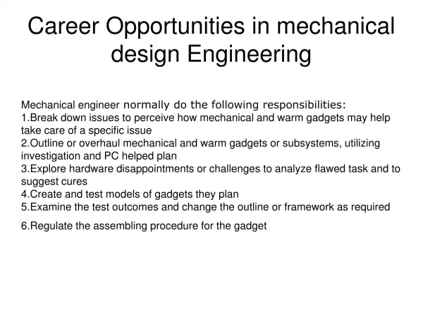
Project description It is desired to design a gearbox To get this we first anaylzed the forces and power generated in the internal combustion engine then according to the inpute data like the maximum torque and maximum power gears designed Then by considering the shasfts distans and gears diameters the critical gear mated during the engaging identified Then all diameters of shafts were found out It is important to note that we used some steps through the shafts inorder to reduce the material used in manufacturing At last all the bearings were selected for the most critical condition and all the data and informations were wrote besides .the figures
Gear design There are some important notes to be informed. First we calculated the power generated ,from some principle physics and fluid mechanics. During the engaging of the gears to the higher speeds, the power increases and the torque reduces. For the rear gear we assumed the conditions as well as 1stt gear,inorder to have the worst situation. the assumption for the overload factor was according to the speed of the shaft. when we have low speeds it should be less than 1.5 and when the speed increases ,the unbalanced forces increases and the overload factor shouldn’t be less than 2.The gear strength for live assumed 10^8 cycles & the reliability was set 99%.Temperture factor was not considered. The surface condition factor was almost 1 because of our gear materials. All the gears are from steel but different hard nesses.
Shaft design: Now it is the time to design the shafts. The most important note is the gears weight. For the upper shaft, we assumed concentrated weight at the center of the gears but at the lower shaft because of their large size, we assumed uniform distributed force. The other note is the steps. During the calculation, we saw that there are some parts that can be manufactured with less diameters. saw we considered some steps and used 3mm fillet radius. The fatigue failure was one of the important factor. this is stated after evaluating the other parameters like critical frequency and defelction.the SODERBERG was the relation for the fatigue failure. The deflection would result in larger diameters, so we used one more bearing in each shaft to reduce the deflection. The calculations resulted in the critical condition when engaging the rear or the 1st gear. so we examined the gear 4 in order to reject it as the bad condition then we solved the problem on the base of rear and 1st gear.
Upper shaft: Critical situation is when rear gear is engaged.
Lower shaft: Critical situation is when rear gear is engaged
Deflection considerations(ANSYS) Other gears just vanished. Modeling
Showing the fillets of the steps. Uniform load distribution of the gear.
Stress distribution. (before middle bearing) Stress distribution. (after middle bearing)
Stress distribution. (after middle bearing) Stress distribution. (after middle bearing)
Bearing selection: We were supposed to select 4 bearings ,two for the upper shaft and two for the lower shaft. But when evaluating the deflections we saw that it is worth to try the 3rd bearing for each shaft and reduce the undesirable deflection which can cause force increased during the engaging. So we did it and According to the critical forces, we selected the suitable bearing from SKF online bearing selection for a long life.Ofcourse in bearing selection, its diameters ,mass and cost were considered.