Development of gis -based input data generation program for qual2e modeling
Development of gis -based input data generation program for qual2e modeling. Asia Geospatial Forum 2011 Hotel Mulia Senayan , Jakarta, Indonesia 2011. 10. 18. Cholyoung Lee*, Kyehyun Kim, Yonggil Park Dept. of Geoinformatic Engineering Inha University, S.Korea

Development of gis -based input data generation program for qual2e modeling
E N D
Presentation Transcript
Development of gis-based input data generation program for qual2e modeling Asia Geospatial Forum 2011 Hotel MuliaSenayan, Jakarta, Indonesia 2011. 10. 18 Cholyoung Lee*, Kyehyun Kim, Yonggil Park Dept. of Geoinformatic Engineering Inha University, S.Korea (khsakura82@inhaian.net) † This work was researched by the supporting project to educate GIS experts
Background Conclusion 1 5 Objective 2 Methodology 3 Results & Discussion 4 Contents
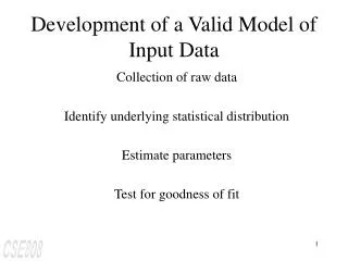
Necessity of Development of WQ Modeling Program • Water quality modeling program can predict a change of future WQ quantitatively • Then, the predicted WQ is used as a basis of setting up a WQ goal in TMDL Development & Application of QUAL2EModel • QUAL2Emodel is easier to use than others while it has high level of accuracy • Therefore, it has been used widely around the world Absence of Programfor Input Data Generation • To operate WQ model, lots of time and effort are needed to generate input data • The schematic diagram creation should be automated by GIS for convenience Background
Study Contents • To model GIS-based schematic diagram creation processes • To construct a spatial DB & develop module programs • To apply programs to a study area to confirm a operation Objective • Development of a GIS-based input data generation program for efficient operation of the QUAL2E model Objective
Methodology 1 2 3 4 6 5 • Entire Study Process Schematic Diagram Creation Process Modeling Design & Construction of Spatial DB Design & Development of Module Programs Development of Integrated GUI Application to Study Area Results & Discussion
Schematic Diagram Creation Process Modeling Identification of general creation process for QUAL2Emodel Measuring location (for calibration) Point pollution sources Withdrawals Methodology ※ ‘Easy to know – Hydrology · WQ Modeling’, NIER(2006) <Example of watershed and stream selection> <Example of drawn schematic diagram (Main/Tributary)> - 6 -
Modeling of GIS-based Schematic Diagram Creation Process By literature research with QUAL2E manual and related studies Methodology • Selection of target watershed on framework data (e.g. watershed/drainage area map) • Inquiry of rivers/streams included in target watershed Selection of Target Watershed • Selection of target rivers/streams (main/tributaries) • Definition of Head-Water and outlet locations Selection of Target Section • Calculation of accumulation distance from HW to outlet • Determination of Partition distance • Generation of elements at each equidistance location along to stream network Equidistance Element Partitioning • Definition of each element’s type (1:HW, 2:Stream, 3:Upper junction, 4:Junction, 5:Outlet, 6:Point Load, 7:Withdrawal) • Definition of hydrologic reach by referring to hydrologic data Definition of Element’s Attribute • Mark of water quality measurement location (for calibration/verification) Mark of WQ Measurement Location - 7 -
Design and Construction of Spatial DB (1/2) Definition of the spatial data necessary for each step Methodology - 8 -
Design and Construction of Spatial DB (2/2) Construction of the spatial DB by collecting utilizable data Methodology * MLTM – Ministry of Land, Transport and Maritime affairs/ ** ME – Ministry of Environment - 9 -
Design & Development of Module Programs Design of modules necessary in individual processes Definition of each work process in the form of data-flow-diagram Methodology <DFD for project management> <DFD for selection of target watershed> <DFD for selection of target section> - 10 -
Methodology • Development of Integrated GUI • The program development environment • Operating System – Microsoft ‘Windows 7’ • Integrated Development Interface – Microsoft‘Visual Studio 2010’ • Libraries forGIS Function implementation – ESRI‘ArcObjects 10’ [Programming] - 11 -
<User window for new project generation> Methodology • Development of Integrated GUI • Use of basic interface design offered from .NET framework • Implementation of each user window according to the design Menu GIS Tools Table of Contents Main Map Display Panel <IntegratedGUI &menu> - 12 -
Methodology • Application to Study Area • Chungju Dam Downstream Watershed • A portion of Han River basin • Inflows of large amounts of pollution loads • Chungju city • Pop. & Ind. are concentrated • 2 target streams • Han River (Main) • Youngduk Stream (1st trib.) • Total lengthof target section • About44 km • Divided at each 1 km interval along the stream <Study area for program application> - 13 -
Results & Discussion • Result of Program Development • Confirmation of program operation (1/3) • Inquiry of related spatial data stored in the spatial DB • Selection of target watersheds through the program’s interface <Result of target watershed selection> <Result of spatial data inquiry> - 14 -
Results & Discussion • Result of Program Development • Confirmation of program operation (2/3) • Automatic extraction of target streams by geo-processing tools • Adjustment of target section by modifying the HW/OL locations <Result of target section selection > <Result of Automatic extraction of target streams> - 15 -
Results & Discussion • Result of Program Development • Confirmation of program operation (3/3) • Automatic equidistance element partitioning • Automatic input of element’s geometric & hydrologic attributes <Result of equidistance element partitioning> <Result of hydrologic attribute input> - 16 -
Results & Discussion • Result of Schematic Diagram for Input Data Generation • GIS-based schematic diagram creation • A total of 44 element grids for the QUAL2E modeling • As shp file format in that contained the vectors <Results of the schematic diagram creation (element numbers, type numbers, reach numbers)> - 17 -
Results & Discussion • Result of Schematic Diagram for Input Data Generation • Attributes of schematic diagram • Stream name • Element number • Element name • Element order • Element’s type number • Reach number • Reach name • Hydrologic information • WQ survey information • Etc. <Result of attributes stored in the schematic diagram> - 18 -
Results & Discussion • Discussion on Result • Enhancement of convenience • It could be created with simple manipulation on the GIS-basedGUI • It is expected to decrease investment of manpower and budget • Improvement of accuracy • The result can be easily linked with other GIS-based related data • Also, it is possible to define the exact element type by an overlay • It is expected to create more accurate and practical input data • Confidence of WQ modeling result in TMDLwork will be increased - 19 -
Results & Discussion • Limitation of Study • Revision of program errors • Program errors occurred in which stream shapes are irregular • It is needed to be stabilized through inspections on various test-bed • Expansion of spatial DB • The spatial DB should be extended for applications on other sites • Some of spatial data should be newly created(ex. KRF, etc.) • The existing data should be verified to assure the accuracy • Full automation of input data generation processes • It is needed to develop an automatic linkage method between the developed program and pollution sources/loadsDB - 20 -
Conclusion GIS-based input data generation program for QUAL2E modeling The input data generation program was developed Through process modeling, design and implementation Convenience & accuracy of input data generation will be enhanced Efficiency of TMDL work might be increased by using the program In the future study, Revision of the program errors to improve performance Expansion of the spatial DB for applications on various sites Development of linkage and generation methods for full automation Conclusion - 21 -
Thank You ! Q & A