TOWARDS A VIRTUAL REALITY PROTOTYPE FOR FUEL CELLS
TOWARDS A VIRTUAL REALITY PROTOTYPE FOR FUEL CELLS. Steven Beale Ron Jerome National Research Council Anne Ginolin Institut Catholique d’Arts et Métiers Martin Perry, Dave Ghosh Global Thermoelectric Inc. Introduction.

TOWARDS A VIRTUAL REALITY PROTOTYPE FOR FUEL CELLS
E N D
Presentation Transcript
TOWARDS A VIRTUAL REALITY PROTOTYPE FOR FUEL CELLS Steven Beale Ron Jerome National Research Council Anne Ginolin Institut Catholique d’Arts et Métiers Martin Perry, Dave Ghosh Global Thermoelectric Inc. Institute for Chemical Process and Environmental Technology
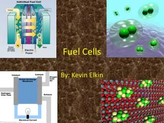
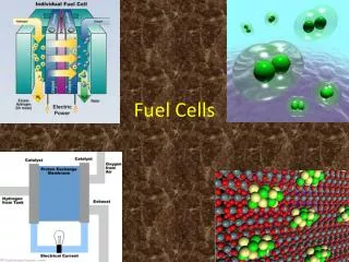
Introduction • Fuel Cells convert chemical energy (hydrogen and oxygen) to electrical energy • Potential replacement for IC engines • National Fuel Cells Initiative: Kyoto summit • Three main parts: Anode, cathode, electrolyte • Solid Oxide Fuel Cells (SOFC’s) can use methane/natural gas in place of hydrogen • Built in stacks of 10-50 cells: Connected in parallel hydraulically; electrically in series Institute for Chemical Process and Environmental Technology
Introduction • SOFC’s operate at up to 1000 ºC • If supply of fuel and air non-uniform, reaction rates and hence temperatures will vary • Temperature uniformity important: If too cold, cell reaction shuts down; Too hot, mechanical failure • Current work to model fluid mechanics (mechanical design). Goal: Uniform delivery of air and fuel to the membrane-electrode assembly • Chemistry not considered at present time Institute for Chemical Process and Environmental Technology
Introduction • Single cell model • Stack model: 10-50 cells. Two approaches • Direct Numerical Simulation (DNS). • Distributed Resistance Analogy (DRA) • For the DNS require large amounts of storage and memory • Certain details lost with the DRA • Several different DRA implementations are possible Institute for Chemical Process and Environmental Technology
DRA approach F is a ‘distributed resistance’ obtained from theory, experiments, or detailed numerical simulations. ri arevolume fractions of air and fuel. Institute for Chemical Process and Environmental Technology
Determination of resistance term • Many internal flows are correlated in the form;where the Reynolds number is written in terms of a “hydraulic diameter”The distributed resistance is just, Institute for Chemical Process and Environmental Technology
Example: Plane duct For a plane duct:For more complex geometries must use numerical integration empirical correlations Institute for Chemical Process and Environmental Technology
PHOENICS settings • Used PHOENICS VR to construct SOFC stack model • Diffusion terms turned off using Group 12 patches GP12DFE etc. for DRA • Source term with PATCH type PHASEM in momentum equations, and Coefficient C = rF/r • 2-D flow imposed in core (w = 0) Institute for Chemical Process and Environmental Technology
Phase 2 CFD modelling begins Phase 1 ends Phase 1 CFD modelling begins Results Source: http://www.globeinvestor.com/ Institute for Chemical Process and Environmental Technology
Results • Results of flow calculations for 24 designs were displayed as 3-D VRML files using a secure web site to the client in Calgary across internet. • This allowed us to work together “at a distance” • Images were also displayed locally to client in Ottawa using NRC Virtual Reality (VR) wall • SOFC stack completely redesigned as a result of this work Institute for Chemical Process and Environmental Technology
Inlet manifold Results Fuel cell stack Exit manifold FLOW OUT FLOW IN Institute for Chemical Process and Environmental Technology
NRC Virtual Reality Wall Institute for Chemical Process and Environmental Technology
Pressure in SOFC manifolds and stack Institute for Chemical Process and Environmental Technology
Velocity vectors in manifolds and stack NB: Vector scale different in stack from in manifolds Institute for Chemical Process and Environmental Technology
Discussion • Geometry is quite simple, but flow in inlet manifold complex; Pressure maximum at front of step. Due to horizontal inlet • Flow within the core of this SOFC stack is uniform, i.e., design is good. Little variation in vectors, in spite of inlet design • Core flow is a low Reynolds number (creeping) flow, driven primarily by the pressure gradient • Pressure drops consistent with values based on theory • Flow in outlet manifold is less complex than inlet: Size and form less critical. Institute for Chemical Process and Environmental Technology
Discussion • Gradient across stack is uniform horizontal. • In manifolds gradient is relatively small and decreases with height - due to injection/suction • Manifold losses are in many cases quite significant, with substantial variations observed, depend on particular configuration under consideration. • For uniform flow the ratio of DPstack/DPmanifolds should be large. • Parametric studies identified which parameters important - allowed for the stack design to be optimised. Institute for Chemical Process and Environmental Technology
Comparison of DRA and DNS Institute for Chemical Process and Environmental Technology
Comparison of DRA and DNS approaches • DRA and DNS results are similar with minor systematic deviations. • Details of velocity profile lost with the DRA. • If core resistance is small, inertial effects become significant: Pressure and velocity less uniform. • For tall stacks need large pressure gradient within core, so inertial effects due injection/suction of working fluid from manifolds does not lead to starvation at top of core. • Various DRA approaches are possible. Minor differences occur due to convection terms. Institute for Chemical Process and Environmental Technology
Conclusions • DRA model may be used as an engineering tool to design SOFC's with a measure of confidence: Certain details of flow field are lost. However combines computational speed with accuracy • Certain SOFC models superior. • Back pressure across stack should be large to maintain uniformity of pressure and velocity across core. • Geometric features by which this may be achieved were identified using parametric studies • SOFC design re-configured as a result of CFD. Institute for Chemical Process and Environmental Technology
Future (current) work • SOFC’s with more complex passages. • Flow of two working fluids, combined with inter-fluid heat transfer and Ohmic heating. • Initial anlysis suggests the conventional DRA for heat transfer may need to be modified due to low Reynolds number effects. • Concurrent display and manipulation of graphics data, locally on VR walls, and across the country via CA*net 3. • Experimental facilities to gather empirical data and conduct flow visualisation studies for model validation. Institute for Chemical Process and Environmental Technology