Download
1 / 18
190 likes | 392 Vues
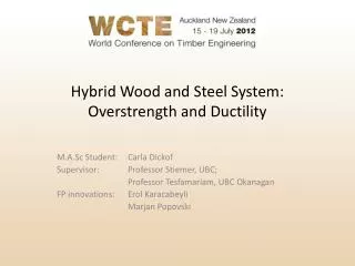
Hybrid Wood and Steel System: Overstrength and Ductility. M.A.Sc Student: Carla Dickof Supervisor: Professor Stiemer, UBC; Professor Tesfamariam , UBC Okanagan FP innovations: Erol Karacabeyli Marjan Popovski. Project Description. Goal :

E N D
Hybrid Wood and Steel System: Overstrength and Ductility M.A.Sc Student: Carla Dickof Supervisor: Professor Stiemer, UBC; Professor Tesfamariam, UBC Okanagan FP innovations: Erol Karacabeyli Marjan Popovski
Project Description Goal: Analyse and provide guidelines for the design of the hybrid seismic force resisting system, steel moment frames with infill wood shear walls Hybrid System of Interest: • Hybridize steel and wood into a vertical seismic force resisting system. • Focus on steel moment frames with a wood infill wall system • Address material incompatibilities with special attention to hydroscopic properties in wood • Provide values for equivalent static seismic design of system
Hybrid System: Base Building Building Plan Frame Elevation
Hybrid System: Parameters Infill Case 1 Infill Case 2 Infill Case 3
Bare Frame Design • Steel moment frame to be designed based with NBCC ductility requirements • Infill walls to be added and compare the response of the frame and the response of plain wood walls
Infill Walls: Midply Shear Walls Midply walls have higher strength compared to standard plywood shear walls • Nails in double shear • Nail head does not pull through sheathing • Increased nail edge distance Failure of walls occurs through buckling of studs
Infill Walls: CLT Walls • Approximated as elastic perfectly plastic with plasticity model • Elastic properties determined using composite theory • Strength limits determined from product data • Plain CLT systems show all deformation in connectors • Confinement from surround frame may cause deformation in the panel • Shear and Rocking • Pure Rocking Pure Shear
Connection between Wall and Frame • Nailed bracket connection developed for CLT walls • Bracket behaviour is independent in different directions • Confinement also provided along edges of panel to provide confinement using “gap” elements
Pushover Results Effect of Infill Panel Type: Single Storey Single Bay Frame
Pushover Results Effect of Gap Size between Infill Panel and Frame: Single Bay Single Storey Frame
Pushover Results Effect of Moment Frame Ductility: 3 Storey Steel for all Infill Configurations
Pushover Results Effect of Number of Storeys: Limited Ductility Steel Moment Frames for all Infill Configurations
Pushover Results 3 Storey Frame 9 Storey Frame 6 Storey Frame Ductile Limited Ductility Comparison of Frame and Panel Yield for all Frames and Infill Configurations
NBCC Seismic Factor Definition Overstrength (Ro or Ω) Ductility (Rd or µT) Ductility is the ratio of the displacement at the ultimate load to the displacement at failure Failure is taken as an 80% reduction in strength after the ultimate load has been acheived according to FEMA P695 • Overstrength is the ratio of the design load to the ultimate load of the system • Looking at the innate overstrength in this type of system, the design load is taken as the load at first yield
NBCC Seismic Factors Ductility Factor for all Frames
NBCC Seismic Factors Overstrength Factors for all Frames
Future Work • FEMA P695 guidelines for dynamic analysis • Partial Incremental dynamic analysis • 22 ‘Far-Field’ ground motions
Acknowledgements Our supporters at NewBuildS through NSERC and Canadian Steel Institute of Steel Construction Thanks to everyone at FPInnovations, with special thanks to Dr. Popovski and Prof. Karacabeyli, industrial advisors to the project Special thanks to the supervisors Dr. Stiemer and Dr.Tesfamariam from the University of British Columbia Acknowledgements to UBC grad students: YaldaKhorasani, Mathieu Angers, Hassan Pirayesh, Carla Dickof, Caroline Villiard, BenediktZeisner.