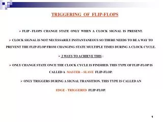
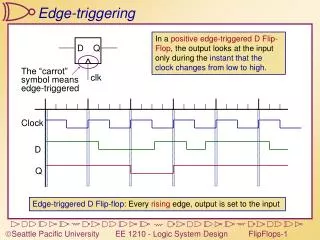
Edge-triggering
D. Q. clk. Clock. D. Q. Edge-triggering. In a positive edge-triggered D Flip-Flop , the output looks at the input only during the instant that the clock changes from low to high. The “carrot” symbol means edge-triggered.

Edge-triggering
E N D
Presentation Transcript
D Q clk Clock D Q Edge-triggering In a positive edge-triggered D Flip-Flop, the output looks at the input only during the instant that the clock changes from low to high. The “carrot”symbol meansedge-triggered Edge-triggered D Flip-flop: Every rising edge, output is set to the input
D Q clk Clock Q D Negative Edge-triggering In a negative edge-triggered D Flip-Flop, the output looks at the input only on the falling edge of the clock. Negative Edge-triggered D Flip-flop: Every falling edge, output is set to the input
D Q en clock en RisingEdgeDetect edge clock clock clock edge d d edge Triggering on an Edge We want to briefly enable the FlipFlop whenever we find a rising edge Edge detection using the time delay through an inverter In reality, this will be delayed by the AND gate
D Q en D+En’ D D+(Clk↑)’ D’ D’+(Clk↑)’ D’+En’ D D•En D•Clk↑ D Q Q=1 Q=1 Q=1 Q=0 Q=0 Q=0 clk D’•Clk↑ D’ D’•En D Latch and FF states Level-sensitive (gated) D-latch Edge-triggered D-FF Edge-triggered D-FF with clock omitted
D Q VHDL for D FlipFlops LIBRARY ieee;USE ieee.std_logic_1164.all;ENTITY DFF ISPORT( D : INSTD_LOGIC; CLK : INSTD_LOGIC; Q : INOUT STD_LOGIC); END DFF; Inputs: D and CLKOutput: Q PROCESSlist State of latch can change due to a change in any of these values ARCHITECTURE behavior OF DFF ISBEGIN PROCESS(CLK) BEGINIF RISING_EDGE(CLK)THEN Q <= D;END IF;END PROCESS; END behavior; Continuously monitors CLK, but not D (Q only changes on CLK edge) Wait until the clock has a rising edge Q only changes on rising edge
Q Q R K J S Q Q clk Jt Kt Qt Qt+1 0 0 0 0 0 0 1 1 0 1 0 0 0 1 1 0 1 0 0 1 1 0 1 1 1 1 0 1 1 1 1 0 Hold Reset Set Toggle J-K Flip-Flops We want to eliminate the forbidden state of the R-S Latch (when R and S are both 1).Idea: Q, Q’ are always different. Use them to control the input. J, K act just like Set and Reset, except: When they’re both 1, we get a toggle.
Q J K Q VHDL for J-K FlipFlops LIBRARY ieee;USE ieee.std_logic_1164.all;ENTITY JKFF ISPORT( J,K : INSTD_LOGIC; CLK : INSTD_LOGIC; Q: INOUT STD_LOGIC;QB: OUT STD_LOGIC); END JKFF; Inputs: J,K and CLKOutput: Q and Q’ ARCHITECTURE behavior OF JKFF ISBEGIN PROCESS(CLK) BEGIN IF RISING_EDGE(CLK)THEN IF (J=‘1’ AND K=‘0’) THEN Q <=‘1’;ELSIF (K=‘1’ AND J=‘0’) THEN Q <=‘0’;ELSIF (J=‘1’ AND K=‘1’) THEN Q <= NOT(Q);ELSE Q <= Q;END IF;END IF; QB <= NOT(Q);END PROCESS; END behavior; Continuously monitors CLK, but not J or K (Q only changes on CLK edge) On clock edge, define outputs for all possible inputs
T Q Q+ 0 0 00 1 11 0 11 1 0 Q T Q Q T T D Q Q Q J Q clk clk K Q Clock T Q Toggle Flip-Flops Build a flip-flop that toggles its state on each clock edge whenit is enabled (T is the enable). Q+ is the Q output after the clock changes
D Q R en S Q clear preset preset D Q R D Q R en en S Q S Q clear preset preset Asynchronous Presets and Clears Clear forces the output low regardless of the other inputs. Preset forces the output high regardless of the other inputs. Ordinary level-sensitive D-latch Clear - Force S=0, R=1 Preset - Force S=1, R=0 Asynchronous - doesn’t matter whether clock is high or low
Clk D D Q D Q Clk Racing the clock Real signals don’t change instantly D is changing during the rising edge of Clk. Is a ‘1’ or ‘0’ clocked in? D is changing right after the rising edge of Clk. Is a ‘1’ or ‘0’ clocked in?
setuptime holdtime D Q D Q Clk Setup and Hold Times Setup Time: How long a signal must be stable preceding the clock edge Hold Time: How long a signal must be stable after the clock edge Clk D Setup: PassHold: Pass Setup: FailHold: Pass Setup: PassHold: Fail Setup: Fail Hold: Fail
Clk D 20ns 20ns 5ns 5ns Q 23/13ns 40/25ns Setup and Hold times: Flip Flops 74LS74 PositiveEdge TriggeredD Flipflop • Setup time – 20ns • Hold time – 5ns • Propagation delays - Low to High – 23 ns max, 13 ns typ - High to Low – 40 ns max, 25 ns typ