Hard Drive
Hard Drive. Section Objectives. After completing this section you will be able to: Install or replace a floppy drive Define and explain fundamental hard drive terminology Compare and contrast IDE and SCSI technologies. Floppy Drive Overview.


Hard Drive
E N D
Presentation Transcript
Section Objectives After completing this section you will be able to: Install or replace a floppy drive Define and explain fundamental hard drive terminology Compare and contrast IDE and SCSI technologies
Floppy Drive Overview • The floppy drive subsystem consists of three main parts: (1) the electronic circuits or the controller, (2) the 34-pin ribbon cable, and (3) the floppy drive. • The electronic circuits give the floppy drive instructions. • The electronic circuits can be built into the motherboard or on an adapter. • The floppy cable connects the floppy drive to the electronic circuits. • The floppy drive allows saving data to disk media.
Floppy Media • Disk – also called floppy disk – The media inserted in a floppy drive. • Write-Protect Window– A small window in the corner of a floppy with a sliding tab to open or close the window. If the window is open the disk is write-protected. • 1.44 MB Disks– 3.5” today’s floppy disks.
Floppy Media 1.44MB with write-Protect and high density windows Floppy – Figure 7.1
Floppy Drive Construction • Floppy drives have two read/write heads that place the data onto the disk. • Floppy disks are inserted between the two read/write heads in the floppy drive. The disk turns inside the disk jackets and the floppy drive heads physically touch and scan the disks to read and write data. • Over time, the read/write heads become dirty. When a technician sees read/write errors occurring the first step is to clean the read/write heads.
Floppy Disk Geometry • When a disk is formatted concentric circles calledtracks are drawn on that disk. 1.44MB disks have 80 tracks. • Sector – Tracks are further subdivided into pie-shaped wedges. A sector is the section defined between a tract and an intersecting line and holds 512 bytes of information. • Cluster – The minimum amount of space one file occupies. On a floppy disk a cluster is 1024 bytes or two sectors.
Floppy Disk Geometry Disk with 80 tracks Floppy – Figure 7.2
Floppy Disk Geometry Sectors and sector numbering Floppy – Figure 7.3
Floppy Drive Installation Installation of floppy drives is simple after doing some preliminary homework: • An available drive bay • An available power connection • A motherboard floppy connector available or install an additional adapter • A floppy cable
Floppy Drive Installation Floppy Connector on Motherboard Floppy – Figure 7.4
Floppy Drive Configuration Floppy drive cable Floppy – Figure 7.5
Floppy Drive Installation • Pin 1 on the cable attaches to Pin 1 on the connector. • Pin 1 is identified by a red stripe on the cable. • Most manufacturers identify Pin 1 in writing on the motherboard. • Installing the floppy is mounting the drive to the case and connecting the cable from the drive to the motherboard or adapter.
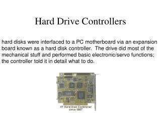
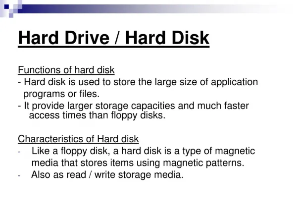
Hard Drive Overview • Hard drives are a popular devices for storing data. • The hard drive subsystem can have up to three parts: • The hard drive • Cables that attach to an adapter or the motherboard • Control circuits located on an adapter or the motherboard
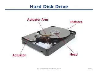
Hard Drive Geometry • Components of a Hard Drive: • Platters are multiple hard metal surfaces contained in the hard drive. • Read/Write Headswrite and read the 1s and 0s to and from the hard drive surface. • Head Crash– When a read/write head touches the hard drive platter. • Track – Concentric circle on a hard drive platter. • Cylinder – One corresponding track on all surfaces of a hard drive. • Sectors – Each track is divided into sectors of 512 bytes.
Hard Drive Geometry Hard Drive Geometry IDE/SCSI – Figure 7.6
Hard Drive Geometry Cylinder versus tracks IDE/SCSI – Figure 7.8
Hard Drive Interfaces Overview • There are two major hard drive interfaces: • IDE (integrated drive electronics) – Also known as ATA (AT Attachment) standard. IDE is most common in home/office computers. • SCSI (small computer system interface) – SCSI is most common in network servers.
IDE (Integrated Drive Electronics) • IDE (Integrated Drive Electronics)is used with hard drives, as well as tape, Zip, CD and DVD drives. • Two types of IDE • PATA (Parallel ATA) – Older ATA type. PATA uses a 40-pin cable to connect the IDE hard drive to the motherboard or an adapter and transfers 16 bits of data at a time. • SATA (Serial ATA) –Is a point to point interface in which each device connects to the host through a dedicated link and has the entire interface bandwidth. • ATA-1 – Original IDE interface standard. • ATA-2 – Faster transfer rates than ATA-1. • DMA mode(direct access mode) – DMA is supported by ATA-2. It allows data transfer between RAM and the hard drive without going through the CPU. • UDMA (ultra DMA) – Also known as bus master DMA. Latest type of DMA.
IDE (Integrated Drive Electronics) IDE PATA Standards IDE/SCSI – Table 7.2
SCSI (Small Computer System Interface) • SCSI (Small Computer System Interface)is an interface standard that connects multiple small devices to the same adapter via a SCSI bus. • SCSI busis the bus shared by all devices that attach to one SCSI adapter. • Host Adapterconnects the SCSI device to the motherboard and coordinates the activities of other devices connected.
SCSI (Small Computer System Interface) SCSI standards IDE/SCSI – Table 7.3
Drive Configuration Overview • The configuration of a hard drive usually includes setting jumpers on the drive, terminating properly, and performing a few software commands.
PATA IDE Device Configuration • The steps for installing a PATA device: • Do not remove the device from the anti-static bag until you are ready to install. • Follow proper anti-static procedure. Touch the device by the sides and do not handle the electronics or connectors. • Turn off the power and remove the power cord. • Configure jumpers according to the number of devices to be attached to the cable. • Mount and secure the device. Attach the cables. • Configure BIOS if needed. • If the device is a hard drive prepare it as specified in the chapter.
PATA IDE Device Configuration • PATA IDE Hard Drives are normally configured using jumpers. • Single IDE setting is used when only one devices connects to the IDE cable. • Master IDE settingis a jumper setting used to configure an IDE device and is the controlling device on the interface. • Slave IDE settingis an IDE setting for the second device added to the IDE cable. The device should be a slower device than the master. • Cable Selectis a setting used on IDE devices when a special cable determines which device is the master and which one is the slave. • DASP (Drive Active/Slave Present)is a signal in the ATA interface of the IDE connector that is used to indicate the presence of a slave IDE device.
IDE Device Configuration IDE Motherboard Connectors IDE/SCSI – Figure 7.18
IDE Device Configuration Two PATA devices configured as cable select IDE/SCSI – Figure 7.21
Serial ATA (SATA) Installation • Serial ATA drives are easy to install. • Serial ATA drives do not have any master/slave, cable select, or termination settings. • Uses a small 7-pin connector that attaches between the serial ATA controller and the serial ATA drive. • Installation instructions for serial ATA drives can be found on page 217.
Serial ATA (SATA) Installation Installed SATA hard drive and adapter IDE/SCSI – Figure 7.25
SCSI Configuration • A SCSI device is configured by: • Setting the proper SCSI ID • Terminating both ends of the SCSI chain • Connecting the proper cables • A SCSI IDis the priority number assigned to each device connected by a SCSI chain.
SCSI ID Configuration • Standard SCSI devices recognize SCSI IDs 0 through 7. • Wide SCSI devices recognize SCSI IDs 0 through 15. • Power on all external SCSI devices before powering on the computer. • Each SCSI device must have a unique SCSI ID. • SCAM (SCSI Configured AutoMatically) allows for automatic SCSI ID assignment.
SCSI ID Configuration SCSI ID settings (most significant bit to the left) IDE/SCSI – Table 7.5
SCSI ID Configuration Two Internal SCSI Devices – SCSI IDs IDE/SCSI – Figure 7.27
SCSI ID Configuration Two External SCSI Devices – SCSI IDs IDE/SCSI – Figure 7.28
SCSI Termination • SCSI termination is performed in several different ways: • By installing a SIPP • By installing a jumper • By setting a switch • By installing a terminator plug • By installing a pass-through terminator • Through software
SCSI Termination IDE/SCSI – Table 7.6
SCSI Termination SCSI termination IDE/SCSI – Figure 7.29
SCSI Termination Today’s SCSI Terminators: pass through terminator and 68-pin active terminator IDE/SCSI – Figure 7.31
SCSI Termination SCSI Symbols IDE/SCSI – Figure 7.32
SCSI Termination Two internal SCSI devices - termination IDE/SCSI – Figure 7.33
SCSI Termination Two external SCSI devices - termination IDE/SCSI – Figure 7.34
SCSI Termination Internal and external SCSI devices - termination IDE/SCSI – Figure 7.35
SCSI Cables • SCSI cabling allows multiple devices to be connected to one SCSI host adapter and share the same SCSI bus. • Most internal SCSI-1 and SCSI-2 cables are 50-pin ribbon cables. They are also known as an A cable. • Internal SCSI-3 cables are 68-pin ribbon cables. • When installing multiple SCSI devices, install one device at a time. • Always avoid using the cheaper, thinner SCSI cables. They are more susceptible to outside noise.
SCSI Cables Internal SCSI cables IDE/SCSI – Figure 7.36
SCSI Cables External SCSI cables IDE/SCSI – Figure 7.37
SCSI Cables SCSI cables and connectors IDE/SCSI – Table 7.7
Laptop Storage Devices • Laptops can use IDE or SCSI hard drives. • Laptop IDE hard drives are installed using two methods: • Proprietary installation is installed in a location that cannot be changed, configured, or moved very easily. • Removable IDE hard drives with a laptop are installed or removed through a 44-pin connector.
System BIOS Configuration for Hard Drives • Hard drives are configured through the Setup program with a drive type number. • IDE hard drives are normally configured using the Auto-Detect feature included with BIOS. This feature automatically determines the drive type for the system. • For SCSI hard drive installation the most common CMOS setting for the hard drive type is none or type 0.
Hard Drive Preparation Overview • Two steps to hard drive preparation: • Partition • High-Level Format
Partitioning • Partitioning divides a hard drive so that the computer system sees more than one drive. • FDISK is a command used in DOS and Windows 9x to partition a hard drive. • Disk Administrator – Windows NT/2000/XP also allow partitions to be set up using the Disk Administrator program. • A File Systemdefines how data is stored on a drive. • FAT (File Allocation Table)is a method of organizing a computer’s file system. • FAT16 file system is supported by DOS, Windows 9x, NT, 2000, and XP. • FAT32file system used by Windows 95 Service Release 2, Windows 98, Windows 2000, and XP that supports hard drives up to 2TB in size. • NTFS (NT File System)file system used with Windows NT, 2000, and XP.