Hard Drive Technologies
Hard Drive Technologies. Chapter 9. Overview. In this chapter, you will learn to Explain how hard drives work Identify and explain the different hard drive interfaces Configure BIOS for hard drives and controllers Troubleshoot hard drive installation. How Hard Drives Work. The Hard Drive .

Hard Drive Technologies
E N D
Presentation Transcript
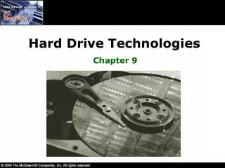
Hard Drive Technologies Chapter 9
Overview • In this chapter, you will learn to • Explain how hard drives work • Identify and explain the different hard drive interfaces • Configure BIOS for hard drives and controllers • Troubleshoot hard drive installation
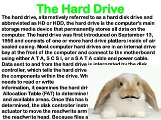
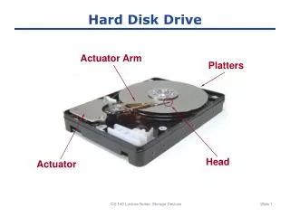
The Hard Drive • All hard drives are composed of individual disks or platters, with read/write heads on actuator arms controlled by a servo motor • The platters are made up of aluminum, and are coated with a magnetic medium • Two tiny read/write heads service each platter
The Hard Drive • The closer the read/write heads are to the platter, the more densely the data packs on to the drive • Hard drives use a tiny, heavily filtered aperture to equalize the air pressure between the exterior and interior of the hard drive
Data Encoding • Hard drives store data in tiny magnetic fields called fluxes • The flux switches back and forth through a process called flux reversal • Hard drives read these flux reversals at a very high speed when accessing or writing data • Fluxes in one direction are read as 0 and the other direction as 1
Data Encoding • The various encoding methods used by hard drives are • Frequency modulation (FM) – places a timing bit before every data flux, taking up lots of disk space • Modified frequency modulation (MFM) –places timing bits after two consecutive zeros, reducing the number of timing bits
Data Encoding • More encoding methods used by hard drives are • Run length limited (RLL) – Here data is stored using ‘runs’ that are unique patterns of ones and zeros • Partial Response Maximum Likelihood (PRML) – It uses a powerful, intelligent circuitry to analyze each flux reversal and identify the type of flux reversal read
Arm Movement in the Hard Drive • The stepper motor technology and the voice coil technology are used for moving the actuator arm • Moves the arms in fixed increments or steps • The voice coil technology uses a permanent magnet surrounding the coil on the actuator arm to move the arm With a stepper motor it was important to park the drive in a nondata area to prevent damage to the surface of the drive. Today that is not necessary with voice coil technology.
Geometry • Geometry is used to determine the location of the data on the hard drive • The geometry for a particular hard drive is described with five special values: • Heads • Cylinders • Sectors per track • Write precomp • Landing zone
Heads • Heads • Number of read/write heads used by the drive to store data • Two heads per platter (top and bottom) • Most hard drives have an extra head or two for their own usage, so the number may not be even
Cylinders • Cylinders • Group of tracks of the same diameter going completely through the drive
Sectors per Track • Sectors per track • Number of slices in the hard drive • 512 bytes per sector
Geometry • Write precompensation cylinder • Obsolete • The specific cylinder from where the drive would write data a little farther apart • Sectors towards the inside of the drive would physically occupy less space than sectors on the outside of the drive. Therefore, older drives would write data farther apart on the outside cylinders. • Landing zone • Unused cylinder as a ‘parking place’ for read/write heads • Referred to as Lzone, LZ, Park • Meaningless in today’s PCs
The Big Three • CHS refers to Cylinders, Heads, Sectors/track • You used to have to manually enter this information in CMOS, but now drives have that information on the drive itself and the BIOS queries it automatically • Talk the talk: • “What’s the CHS?” • “What’s the geometry?”
Hard Drive Interfaces • Integrated Drive Electronics (IDE) / Enhanced IDE (EIDE) interfaces dominate today’s market • Parallel ATA (PATA) drives dominate the industry • Serial ATA (SATA) since 2003 • Small Computer System Interface (SCSI) interfaces are fading away
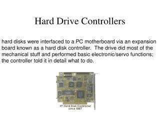
Early Hard Drives • Early drives did not have the controller card integrated with the drive. The hard drive controller was a separate card • To prepare an older drive you had to erase all the geometry (including the data) and reinstall the geometry using a low-level format • Then you had to enter the geometry into CMOS
IDE / EIDE • Integrated Drive ElectronicsandEnhanced IDE • Hard drive controller is integrated with the drive • Uses the AT Attachment(ATA) interface and a 40-pin ribbon cable • Everyone calls ATA drives IDE • EIDE added some enhancements to IDE • Higher capacities • Support for non-hard drive devices like CD-ROMs • Support for up to 4 hard drives • ATA, IDE, and EIDE are used interchangeably today to describe all ATA devices
IDE/EIDE • EIDE drives connect to the computer via a 40-pin cable and a controller • The controlleracts as an intermediary between the hard drive and the external data bus • When the BIOS talks to the hard drive, it talks to the circuitry onboard the hard drive • But we still call the connection on the motherboard the hard drive controller (a misnomer) • Most PCs provide two onboard EIDE controllers to support up to four hard drives • Use the primary controller if you are only connecting one device • The other controller is the secondary controller
Controller Cards Expansion controller card On board controller
IDE/EIDE Cabling EIDE Drives: • EIDE drives connect to the controller via a simple 40-pin cable • A single cable can connect up to two hard drives: master and slavebased on the jumper settings. • Cable-select may be set on both drives if you have a cable-select cable Master or Slave – it doesn’t matter which connector you use.
Jumpers and Labels Master and Slave jumpers
ATAPI • Advanced Technology Attachment Packet Interface (ATAPI) • Extension to the ATA specification • Enables non-hard drive devices to connect to the PC via ATA controllers • Same rules on jumper settings • Hard drives get BIOS thru the System BIOS and CMOS • Non-hard drives get BIOS thru an option ROM or software driver
Serial ATA • Serial ATA (SATA) creates a point-to-point connection between the device and the controller • Data is sent serially • Thinner cables resulting in better air flow and cable control in the PC • Maximum cable length of 39.4 inches compared to 18 inches for PATA cables Data connection Power connection
Serial ATA • More on SATA • Hot-swappable • Throughput of 150 MBps (with potential of 600 MBps) • A parallel ATA device (PATA) my be connected to SATA using a SATA bridge • Add SATA functionality via a PCI card • Only one device per controller
CMOS • The CMOS setup should be updated with the drives geometry after the hard drive is installed in the system: • With today’s hard drives you may simply set the type to Auto and the hard drive and CMOS will work it out – up to four ATA devices may be connected • With much older hard drives you must manually enter all of the geometry – support for only two hard drives maximum
Storage Technologies • Logical Block Addressing (LBA) and Enhanced CHS (ECHS) • LBA/ECHS is an advanced type of sector translation • The onboard circuitry of the drive translates the logical geometry into physical geometry. This function is called sector translation. • LBA provides support for a maximum hard drive size of 8.4 GB
Storage Technologies • LBA and ECHS (continued) • ECHS works the same way as LBA, but has different values • LBA was developed by Western Digital • ECHS was developed by Seagate • Interrupt 13 extensions (INT13) were a set of BIOS commands introduced by Phoenix Technologies • A system with INT13 can handle drives up to 137 GB
Storage Technologies LBA and ECHS (continued): • ECHS works the same way as LBA, but has different values. • LBA was developed by Western Digital • ECHS was developed by Seagate • Interrupt 13 extensions (INT13) were a set of BIOS commands introduced by Phoenix Technologies. • A system with INT13 can handle drives up to 137 GB.
CMOS • The LBA setting for a drive indicates that the drive is capable of logical block addressing • The Normal setting notifies the system to use the physical geometry, rather than the logical geometry • Used with OS’s that don’t use the BIOS such as NetWare and some versions of UNIX • The Large setting indicates that the device is capable of ECHS • Not all systems support ECHS but all systems do support LBA – use LBA!
ATA/ATAPI-6 • INT13 extensions provided an upper limit of 137 GB for hard drive size • ANSI ATA committee has now adopted a new standard called Big Drives with the official name ATA/ATAPI-6 • Supports a maximum size of 144 petabytes (144,000,000 GB)
Transferring Data • Programmable input/output (PIO) and Direct Memory Access (DMA) are the two modes through which ATA devices transfer data to and from the hard drive and memory • It is essential to set the proper PIO mode for the drives to get the best performance out of them • PIO modes define the data transfer rate between RAM and the hard drive • The slower of the PIO modes supported by the hard drive, controller, BIOS, or device driver should be used • DMA data transfers can be 16-bit wide or 32-bit wide
ATA/66 and ATA/100 • Advanced DMA modes are: • Ultra DMA mode 4 (called ATA/66) – 66 MBps • Ultra DMA mode 5 (called ATA/100) – 100 MBps • Ultra DMA mode 6 (called ATA/133) – 133 MBps • The ATA/66 and ATA/100 require special controllers and 80-wire (40-pin) ribbon cables • All higher-end drives can run on lower-end controllers; most controllers can handle lower-end drives
Motherboards • Many motherboards come with a variety of controllers • ATA-66 controllers are usually blue • ATA-100 controllers are usually red • Plug the blue or red connector on the cable into the motherboard, the black connector into the master drive, and the gray connector into the slave drive
80-wire Ribbon Cables • 80-wire ribbon cables still have 40 pins – the extra wires are used to reduce noise ATA/66 and ATA/100 drives can use the 40-pin cable but will operate as an ATA/33 drive.
Device Drivers • ATAPI Devices show up in CMOS but true BIOS support comes from a driver at boot-up • Serial ATA require loading drivers for an external SATA controller and configuring the controller Flash ROM settings for the specific drive
Protecting Data • The most important part of a PC is the data it holds • Companies have gone out of business because of loosing the data on their hard drive • Since hard drives will eventually crash and die, it is important to find a way to save the data when a hard drive fails • This can be done by having multiple hard drives that work together • Redundant Array of Inexpensive Disks (RAID) is one such technology
RAID Level 0 • Disk Striping • Writes data across multiple drives at once • Requires at least 2 hard drives • Does not provide redundancy • If any drive fails, the data is lost
RAID Level 1 • Disk Mirroring/Duplexing is the process of writing the same data to two drives at the same time • Requires at least two drives • Produces an exact mirror of the primary drive • Mirroring uses the same controller • Duplexing uses separate controllers
RAID Level 2 • Disk Striping with Multiple Parity Drives • Not used
RAID Levels 3 and 4 • Disk Striping with Dedicated Parity • Dedicated data drives and dedicated parity drives • Quickly replaced by RAID 5
RAID Level 5 • Disk Striping with Distributed Parity • Distributes data and parity evenly across the drives • Requires at least 3 drives • Most common RAID implementation
RAID Level 6 • Super Disk Striping with Distributed Parity • RAID 5 with asynchronous and cached data capability