Hard Drive Technologies Chapter 9
Hard Drive Technologies Chapter 9. Overview. In this chapter you will learn: Explain how hard drives work Identify and explain ATA hard drive interfaces Identify and explain SCSI hard drive interfaces Describe how to protect data with RAID. Historical/Conceptual. How Hard Drives Work.

Hard Drive Technologies Chapter 9
E N D
Presentation Transcript
Overview • In this chapter you will learn: • Explain how hard drives work • Identify and explain ATA hard drive interfaces • Identify and explain SCSI hard drive interfaces • Describe how to protect data with RAID
Historical/Conceptual How Hard Drives Work
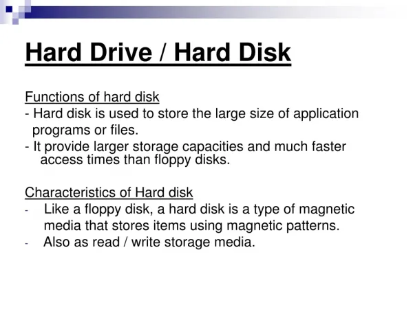
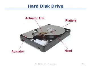
The Hard Drive • Hard drives are composed of individual disks or platters • The platters are made up of aluminum (non-magnetic), and are coated with a magnetic medium • Two tiny read/write heads service each platter one to read top and the other to read bottom.
The Hard Drive • The closer the read/write heads are to the platter, the more densely the data can be packed on to the drive. • Hard drives use a tiny, heavily filtered aperture to equalize the air pressure between the exterior and interior of the hard drive (sensitive for dust). • Platters spin between 3500 and 10,000 rounds per minute (RPM).
Data Encoding • Hard drives store data in binary form. • Binary data stored in tiny magnetic fields (called fluxes) that can be placed in either direction. • The flux switches back and forth through a process called flux reversal • Fluxes in one direction are read as 0 and the other direction as 1 • Hard drives read these flux reversals at a very high speed when accessing or writing data using encoding method.
Data Encoding Method • Encoding methods used by hard drives are • Run length limited (RLL) • Instated of dealing with individual fluxes HD read and write group of flux called run. That are unique patterns of ones and zeros • Can have runs of about 7 fluxes • Partial Response Maximum Likelihood (PRML) • Used by current hard derive. • Uses a powerful, intelligent circuitry to analyze each flux reversal • Can have runs of about 16-20 fluxes • Significantly increased capacity (up to 1TB)
Arm Movement in the Hard Drive Head Actuator Actuator Arm
Arm Movement in the Hard Drive • Only two technologies used for moving the actuator arm. • 1- The stepper motor technology • Moves the arms in fixed increments or steps • Arms parked in non-data area using special parking program. • Only seen in floppies today. • 2- The voice coil or linear motor technology • Uses a permanent magnet surrounding the coil on the actuator arm to move the arm. • When an electrical current passes the coil generates a magnetic filed that moves an actuator in both direction. • Automatically parks drive over non-data area when power removed
Geometry • Geometryis used to determine the location of the data on the hard drive • CHS: Cylinders # , Heads # , Sectors #. • If you open hard drive you would not see the geometry. • Used to be critical to know geometry • Old day, had to manually enter into CMOS • Today, Geometry stored on hard drive • BIOS can query hard drive for geometry data
Heads • Number of read/write heads used by the drive to store data • Two heads per platter (top and bottom) • Most hard drives have an extra head or two for their own usage, so the number may not be even This is track
Cylinders • Cylinder is group of tracksof the same diameter going completely through the drive. • Typically hard drive contains thousand of cylinders.
Sectors per Track • Number of slices in the hard drive • Stores 512 bytes of data. • You can’t divide data into any thing smaller than a sector. • Sector per track is value describe # of sector in each track. 1 2 6 3 5 4
Obsolete Geometry • Might see in older systems • Write pre-compensation cylinder • The specific cylinder from where the drive would start writing data farther apart. • Internal sectors were physically smaller • External sectors physically larger • This identified cylinder where spacing changed • Landing zone • Unused cylinder as a ‘parking place’ for heads • Referred to as Lzone, LZ, Park • Needed for older drives using stepper motors
CHS Exercise (1) • What is the hard drive capacity with the following geometry. • 2100 cyl / 16 heads 63 sectors per track (spt) Answer: • C x H x sectors/track x 512 • 2100 x 16 x 63 x 512 = 1,083,801,600 bytes • Each Kilo byte is 1024 byte (2^10) • 1,083,801,600 / 1024 = 1,058, 400 KB • 1,058, 400 KB / 1024 = 1033.59375 MB • 1033.59375 MB / 1024 = 1.009 GB
CHS Exercise (2) • A "1.44 MB” floppy disk has: • 80 cylinders, 2 heads and 18 sectors/track. • Therefore, its capacity in sectors is computed as follows: • C x H x sectors x 512 • 80 x 2 x 18 x 512= 1474560 bytes (1.44 MB)
IT Technician ATA – The King
Hard Drive Interfaces • Over years many interface existed for hard drive. • ATA interfaces dominate today’s market • Many changes throughout years. • Parallel ATA (PATA) historically prominent • Serial ATA (SATA) since 2003 • Small Computer System Interface (SCSI) • Pronounced “Scuzzy” • Used in many high-end systems
ATA-1 • Parallel ATA • Used a single, 40-pin ribbon cable to connect hard drive to the singlecontroller on motherboard • Max of 2 drives can attach to a single IDE connector : master and slave
Single Master Slave
ATA-1 Max. Capacity • limitation by BIOS • Supported hard drives up to 504 MB.a max of 1024 cylinders, 16 heads and 63 sectors per track (CHS). • 1024 cylinders*16 heads* 63 sectors/track *512 bytes/sector = 528 million bytes = 504 MB (528 million/ 2^20)
ATA-1 Speed • To make a Hdrive standard, we must define both the methodand speed at which the data is going to move: • Programmable I/O (PIO) – traditional data transfer, is an I/O addressing scheme where CPU talks directly to Hdrive via BIOS to send and receive data. • 3.3 MB/s to 8.3 MB/s • DMA – Direct Memory Access • 2.1 MB/s to 8.3 MB/s • Called PIO Mode and DMA Mode
PIO and DMA mode • DMA modes defined a method to enable Hdrives to talk to RAM directly usingold-style DMA commands(called single word DMA) • 3 ATA single word DMA modes (which were slow): • Single word DMA mode 0 : 2.1 MBps • Single word DMA mode 1 : 4.2 MBps • Single word DMA mode 2 : 8.3 MBps • At boot: BIOS queried Hdrive to see what modes it could use and would then automatically adjust to the fastest mode.
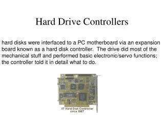
ATA-2 • Commonly called EIDE -enhanced Integrated Drive Electronics - (though a misnomer). • Added second controller to allow for four drives instead of only two. • Added ATAPI that enabled non-hard drive device such as CD-ROM to connect to the PC via ATA-2 controllers. • Broke the 504 MB barrier using Logical Block Addressing (LBA).
ATA-2 Capacity • With LBA Hdriveliesto computer about its geometry through an advanced type of sector translation. • To get up to 8.4 GB instead of 504 MB • So, the ATA-2 spec was designed to have 2 geometries: • the physical geometry defined the real layout of CHS inside drive. • Logical geometry described what the drive told CMOS.
Sector translation • When data was being translated to and from the drive, the onboard circuitry of the derive translated the logical geometry into the physical geometry. • Since the BIOS CHS allows for fewer cylinders, the actual cylinders reported by the drive are divided by 2, 4, 8, or 16 to bring the number below 1024 and the number of heads is multiplied by that same number.
ATA-3 • Self-Monitoring Analysis and Reporting Technology • S.M.A.R.T. • Helps predict when a hard drive is going to fail by monitoring the hard drives mechanical components. • No real change in other stats
ATA-4 • Introduced Ultra DMA Modes • Ultra DMA Mode 0: 16.7 MBps • Ultra DMA Mode 1: 25 MBps • Ultra DMA Mode 2: 33.3 MBps • Ultra DMA Mode 2, the most popular of ATA-4 DMA model, also called ATA/33
Interrupt 13 Extensions (INT 13) • The original ATA-1 standard allowed for hard drives up to 137 GB! • 504 MB limit was caused by old AT BIOS , AND BIOS not ATA standard could support only 504 MB. • LBA was a work-around that told Hdrive to lie to BIOS to get it up to 8.4 GB • Eventually Hdrives started edging close to LBA limit. BIOS makers needed to fix BIOS. It was done by a new set of BIOS commands called INT13 extensions
INT 13 extension • Developed by PhoenixTechnologies • Phoenix came up with a new set of BIOS commands called Interrupt 13 extension. • It broke the 8.4 GB barrier by ignoring CHS values and feeding LBA a stream of addressable sectors • BIOS must recognize INT 13
ATA-5 • Introduced newer Ultra DMA Modes • Ultra DMA Mode 3: 44.4 MBps • Ultra DMA Mode 4: 66.6 MBps • Ultra DMA Mode 4 is the most popular also called ATA/66 • Used 40 pin cable, but had 80 wires • ATA-5 defined exactly where the controller master and slave drives connected (don’t need jumpers). • Blue connector – to controller • Gray connector – slave drive • Black connector – master drive
ATA-5 • ATA/66 is backward compatible. • You can safely plug an earlier drive into an ATA/66 cable and controller. • if you plug an ATA/66 drive into an older controller , it will work (but not in ATA/66 mode). • The only risky action is to use an ATA/66 controller and Hdrive with a non-ATA/66 cable. It causes data losses.
ATA-6 • “Big Drives” introduced • Replaced INT13 & 24 bit LBA to 48 bit LBA • Increased maximum size to 144 PetaBayte • 144,000,000 GB • Introduced Ultra DMA 5 • Ultra DMA Mode 5: 100 MBps ATA/100 • Used same 40-pin 80 wire cables as ATA-5
ATA-7 • Introduced Ultra DMA 6 • Ultra DMA Mode 6: 133 MBps ATA/133 • Used same 40-pin 80 wire cables as ATA-5 and ATA6 • Didn’t really take off due to SATA’s popularity • Introduced Serial ATA (SATA) • Increased throughput to 150 MBps to 300 MBps
IDE Cables • Integrated Drive Electronics • Ribbon • Rounded • No twist! • 40 pin • 40 pin/80 wires Max speed = 33MB/sec Max speed = 133MB/sec
40 wire IDE ribbon cable 33 MB/sec max 80 wire IDE ribbon cable 133MB/sec max
Motherboard Connections Primary IDE controller is usually faster – ATA/66, 100 or 133. Secondary controller operates at ATA/33 Normally, the IDE controllers Identified as IDE1 and IDE2 on the motherboard Onboard Controllers (2 x 40 pin male ports)
Problems with PATA • PATA problems: • IDE cables block airflow and hinder cooling • Max cable length of 18 inches • Can’t hot-swap PATA drives • Technology has reached the limits of what it can do in terms of throughput • SATA addresses these issues. • SATA derives transfer data in serial bursts instead of parallel.
Serial ATA • Serial ATA (SATA) creates a point-to-point connection between the device and the controller • Hot-swappable • Can have as many as 8 SATA devices • Thinner cables resulting in better air flow and cable control in the PC • Maximum cable length of 40 inches (1 meter) compared to 18 inches for PATA cables
Serial ATA • More on SATA • SATA is backward compatible. • PATA device my be connected to SATA cable using a SATA bridge
Serial ATA • More on SATA • Can have as many as 8 SATA devices • Add more SATA functionality via a PCI card • eSATA • External SATA • Extends SATA bus to external devices eSATA Port
SATA Cable 4-wire data cable 7 pin connector Motherboard SATA socket
SCSI • Pronounced “Scuzzy” • Used by specialized server machines. • Been around since 70’s • Devices can be internal or external • Historically the choice for RAID • Faster than PATA • Could have more than 4 drives • SATA replacing SCSI in many applications
SCSI Chains • SCSI devices connect together in string of device called chain. • The host adapter is a device that attaches the SCSI chain to the PC • All SCSI devices are divided into internal and external groups • The maximum number of devices, including the host adapter, is 16
SCSI host adapter • PCI host adapter (SCSI controller)
Internal Devices • Internal SCSI devices are installed inside the PC and connect to the host adapter through the internal connector • Internal devices use a 68-pin ribbon cable. Flat and flexible cable. • Cables can be connected to multiple devices • CD-ROM drive is an example of internal SCSI device.