Membrane potential
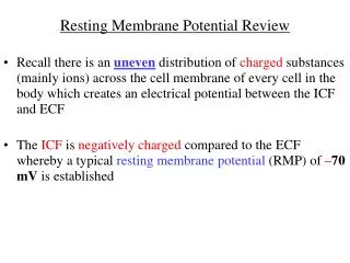
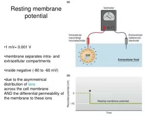
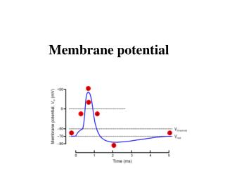
Membrane potential. Electrical potential difference across the membrane is called the membrane potential. The membrane potential of a cell at rest is called the resting membrane potential . Its usual range in neurons is -60 mV to -70 mV.

Membrane potential
E N D
Presentation Transcript
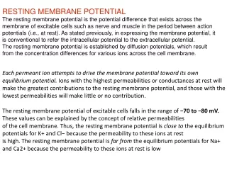
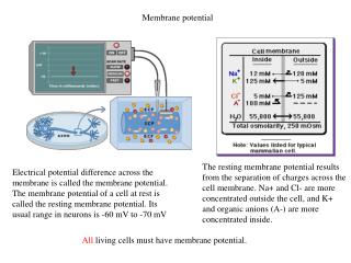
Membrane potential Electrical potential difference across the membrane is called the membrane potential. The membrane potential of a cell at rest is called the resting membrane potential. Its usual range in neurons is -60 mV to -70 mV The resting membrane potential results from the separation of charges across the cell membrane. Na+ and Cl- are more concentrated outside the cell, and K+ and organic anions (A-) are more concentrated inside. All living cells must have membrane potential.
Recording the Membrane Potential The micropipette is used for electrical recording (extracelluar, intracellular, patch), electrical stimulation or delivery of substances. Intracellular recordings in vivo. Group of prof. Amzica, Universite Laval, Quebec, Canada
Patch clamp (E. Neher, B. Sakmann, Nobel 1991) A glass micropipette that has an open tip diameter of about one micrometer, Patchclampmicropipette are prepared in the same way as normal micropipettes but havesmoothsurfacetipsthathelp to form a high resistance seal with the cellmembraneinsteadbreakingthroughit. Patchclampallowsrecording of the currents of single ion channels (indside-out) and electricalbehavior of the entirecell (wholecell). Classical patch clamp setup, with microscope, antivibration table and micro manipulators
Patch clamp Whole cell recording of a nerve cell from the hippocampus. The pipette in the photograph has been marked with a slight blue colour.
Chemical and electrical forces R – gas constant T – absolute temperature F – Faraday’s constant V –potential difference z - valence number of the ion Faraday’s constant is the magnitude of electric charge per mole of electrons.
The Nernst Potential At equilibrium (no net flux of ions): Walter Hermann Nernst born June 25, 1864 in Briesen (Wąbrzeźno), died November 18, 1941 in Zibelle. Received Nobel Prize in Chemistry, 1920r. The Nernst equation V - reversal potential (also known as the Nernst potential).
The membrane potential The membrane potential is the weighted average of each contributing ion's equilibrium potential. Millman equation: Goldman or Goldman-Hodgkin-Katz (GHK) equation: P – relative membrane permeability [m/s] For PNa = 0.04*PK, and neglecting Cl- we get (from the Goldman equation): Vm = -60 mV
Equivalent circuit Equivalent electrical circuit for the electrical properties of the nerve membrane. Each equilibrium potential is represented by a battery across the membrane which has the appropriate polarity and voltage for that ion. In series with the battery is a resistance which is related to the membrane permeability for that ion. The reciprocal of the resistance is conductane (G). Conductance is related to the membrane permeability as follows (using K as the ion in question): The channels for each type of ion are separate and independent. In addition, the membrane is able to store electrical charges, hence it has also capacitance (C).
Sodium-potassium pump In order to maintain a resting potential, the cell cells must keep a low concentration of sodium ions and high levels of potassium ions within the cell. It requires an active transport i.e., the movement of a substance across a cell membrane against its concentration gradient (from low to high concentration). The mechanism responsible for this is the sodium-potassium pump, which pumps three sodium ions out of the cell for every two potassium ions pumped in. Energy (from hydrolysis of ATP to ADP) is required for this process. For neurons, the sodium-potassium pump can be responsible for up to 2/3 of the cell's energy expenditure.
Action potential Action potential (AP) is a transient depolarizatinon of the membrane potential. Early experiments (K.C. Cole i H. J. Curtis, 1939) showed that the membrane becomes almost 50 mV positive inside at the peak of the AP. If the AP was due to transient breakdown in permeability to all ions, it would depolarize membrane to zero, but not beyond. Experiments on AP generation mechanism were performed on on the squid giant axon, which is up to 1 mm in diameter. It provided a great experimental advantage as it allowed to insert voltage clamp electrodes inside the axon. Loligo pealei
Action potential – the sodium impulse Dpependence of the actionpotential on Na ions. A. The peak of the AP decreases with reducion of externalsodiumconcentration. Strongdependence of the maximum on the Na concentrationsuggestlargepermeability to Na+ duringanimpulse. B. Changingexternalsodiumhasverylittleeffect on the restingmembranepotential. Alan Hodgkin and Bernard Katz discovered that AP amplitude depends on external Na+. They put forward a hypothesis that transient increase in permeability to Na+ and influx sodium ions to the cell is responsible for AP. It was confirmed by the fact that the peak of AP is near the Na+ equilibrium potential of about +55 mV. Their experiments also showed that repolarization of AP may be related to increase in permeability to K+ and efflux of potassium ions out of the cell.
AP has a threshold Subthreshold depolarizations are compensated by passive efflux of potassium ions out of the cell. If the efflux of potassium ions cannot compensate the active influx of sodium ions to the cell, the membrane reaches the threshold for impulse and action potential is generated.
Action potential - all or nothing Increase in gNa Membrane depolarization Na+ inflow Na+ conductance is involved in a positive feedback relation with the x depolarization. This is reinforcing regenerative relation similar to that between heat and chemical reaction underlying the explosion of a gunpowder. It gives the ‘action’ to the action potential.
Refractory period The action potential is also followed by a brief period of diminished excitability, or refractoriness, which can be divided into two phases. The absolute refractory period comes immediately after the action potential; during this period it is impossible to excite the cell no matter how great a stimulating current is applied. This phase is followed directly by the relative refractory period, during which it is possible to trigger an action potential but only by applying stimuli that are stronger than those normally required to reach threshold. These periods of refractoriness, which together last just a few milliseconds, are caused by the residual inactivation of Na+ channels and increased opening of K+ channels.
Voltage clamp The voltage-clamp technique was developed by Kenneth Cole in 1949 to stabilize the membrane potential of neurons for experimental purposes. It was used by Alan Hodgkin and Andrew Huxley in the early 1950s in a series of experiments that revealed the ionic mechanisms underlying the action potential. This technique permits measurement of the effect of changes in membrane potential on the ionic conductances of the membrane. The voltage clamp is based on the negative feedback mechanism. Membrane potential is measured by Membrane potential amplifier connected to an intracellular electrode and to an extracellular electrode in the bath. The membrane potential signal is displayed on an oscilloscope and is also fed into one terminal of the “feedback” amplifier. This amplifier has two inputs, one for membrane potential (Vm) and the other for the command potential. The command potential, which comes from a signal generator, is selected by the experimenter. The feedback amplifier subtracts the membrane potential from the command potential. Any difference between these two signals is amplified and sent to a current electrode, a thin wire that runs the length of the axon. The clamp circuit produces a current equal and opposite to the ionic current. This can be measured, giving an accurate reproduction of the currents flowing across the membrane.
Hodgkin and Huxley experiment - results A small depolarization is accompanied by capacitive and leakage currents (Ic and Il, respectively). A larger depolarization results in larger capacitive and leakage currents, plus an inward current followed by an outward current. Depolarizing the cell in the presence of tetrodotoxin (which blocks the Na+ current) and again in the presence of tetraethylammonium (which blocks the K+ current), reveals the pure K+ and Na+ currents (IK and INa, respectively) after subtracting Ic and Il. • Fugu (puffer fish) is a sushi dish prepared from the meat containing TTX • Training for fugu chef takes about 3 years, 35 % pass the exam. • In Japam 5-10 persons per year die from fugu poisoning. • Fugu is the only dish that the Japanese Emperor is not allowed to eat
Hodgkin and Huxley experiment - results Ohm’s Law: V = IR Knowing IK, INa, VK, VNa, and V one may calculate gK i gNa. IK, INa may be taken from voltage clamp, VK, VNa are constants, V is set by the experimenter.
Hodgkin and Huxley model - gates Voltage clamp experiments for different values of V allowed to suggest that voltage-gated Na+ channels have two gates, which respond in opposite ways to depolarization. In the resting (closed) state the activation gate is closed and the inactivation gate is open (1). Upon depolarization a rapid opening of the activation gate allows Na+ to flow through the channel (2). As the inactivation gates close, the Na+ channels enter the inactivated (closed) state (3). Upon repolarization, first the activation gate closes, then the inactivation gate opens as the channel returns to the resting state (1). K+ channels have only activation gate which opens slowly upon depolarization. Individual voltage-gated channels may be recorded by patch clamp. They open and close in an all-or-none fashion. Their sum gives a smooth time course of the total current.
Gate model – Hodgkin and Huxley (1952) Closed Open a y - the probability of the gate in the open state, 1-y – the probability of the gate to be in the closed state a, b – rate coefficients 1 - y y b First order kinetics yields: At steady state: Therefore: Substituting this into equation:
Gate model – Hodgkin and Huxley (1952) Integration yields: Steady state Time constant The voltage dependence of the rates and the steady state of the HH model.
Hodgkin and Huxley model From the time course of measured gK i gNa Hodgkin and Huxley found that gK i gNa do not follow simply exp(-t/t) but rather power functions of exp(-t/t). They propopsed: Recalling the gate model:
Hodgkin and Huxley model These equations yield the following solutions for n, m and h: Substituting n,n,h into gNa i gK: because m0 i hinf are neglectably small.
Hodgkin and Huxley model By fitting the equations for gNa, gK to the time records of gNa, gK at various voltages, HH measured and they calculated as follows:
Hodgkin and Huxley model Using numerical methods Hodgkin and Huxley solved HH model equations and obtained remarkable fits between the recorded and calculated action potentials. HH model is considered a greatest achievement in quantitative brain modeling or even in all biological sciences. HH theory also accounts for the conduction of action potential along nerve fibres. From: Hodgkin, A. L., and A. F. Huxley. A quantitative description of membrane current and its application to conduction and excitation in nerve. J. Physiol. London 117: 500–544, 1952. HH model has also some limitations. It describes macroscopic currents but not currents at the level of single channels.
Ca+ currents Two types of calcium channels recorded using patch clamp. A. T-type (transient lub LVA – low voltage activation channel). B. L-Type (long lasting lub HVA – high voltage activated channel).
K+ currents IK(DR)+ IK(A) The greatest diveristy exists among K+ channels. Potassium channels are the main mechanisms for maintaining the equilibrium of the cell and for controlling membrane excitability. Since the potassium equilibrium potential is near the resting membrane potential, activation of K+ channels tend to return the membrane potential to the resting level. IK(C) 1mM[Ca2+]in Delayed rectifier IK(DR) Transient IK(A) Delay current IK(D) Calcium-Dependent IK(C),IAHP Anomalous rectifier IAR; IQ; Ih M current IM Leak IK, leak 1mM[Ca2+]in 1mM[Ca2+]in 1mM[Ca2+]in IK(DR)+IK(A)+IK(D)+IK(C) +IAHP+IM
Expanded version of the equivalent circuit of the cell membrane
Four types of coritcal neurons? Traditionally, there are four types of behavior of cortical neurons and they are assigned to different types of cells: RS – regular spiking, FRB – fast rhythmic bursting, FS – fast spiking, IB – intrinsically bursting. Intracelluar recordings in vivo showed that firing patterns can be transformed from one type into another by slight changes in the membrane potential. a) Intracellular recordings in awake and sleeping cats. b) intracellular recording from cortical neuron in cat under anasthesia. Current injection (b1 – inset) changes the firing pattern. Mircea Steriade,Neocortical Cell Classes Are Flexible Entities. NATURE REVIEWS |NEUROSCIENCE, VOL. 5, pp. 121-134, 2004.