Download
1 / 30
320 likes | 481 Vues
Review of the European XFEL Bunch Compression System Summary. Torsten Limberg. Topics and Speakers. Introduction and Concept T. Limberg Optic and Tolerances W. Decking Simulation Calculations M. Dohlus Tuning T. Limberg

E N D
Review of the European XFEL Bunch Compression SystemSummary Torsten Limberg
Topics and Speakers • Introduction and Concept T. Limberg • Optic and Tolerances W. Decking • Simulation Calculations M. Dohlus • Tuning T. Limberg • Bunch Compression Options M. Dohlus • Diagnostic Overview & FB H. Schlarb • Diagnostic Sections Lay Out C. Gerth • Diagnostic Tools and Optical Replica B. Schmidt & M. Yurkov • Vacuum N. Mildner, T. Wohlenberg, K. Zapfe
Design Goals and Considerations Electron bunches out of the gun:50 A peak current, small energy spread BC system has to convert that to: • 5 kA peak current • < 25 mm Bunch Length (shorter pulses?) • < 1.4 mm-mrad slice emittance • < 1 MeV slice energy spread (stay about a factor of two below that from synchrotron radiation in undulator) • Compensate rf structure wake field induced correlated energy spread as good as possible with rf induced energy chirp for compression (mimimize laser bandwidth) • avoid high gain for micro-bunch instability • avoid big projected emittance (> 2.5 mm-mrad) • < 10% peak current jitter (SASE jitter <10 %) • arrival time jitter has mainly to be measured and taken care of by the experiments
Bunch Compressor Beam Line Optics Diagnostic Section Dogleg (R56 ≈ - 0.015 m) Drift through shielding 18 deg deflection to commissioning dump
W. Decking: To Do List Optics and Tolerances • Include BC Diagnostic Sections in Master Deck • Increase BC chicane middle dipoles distance to include diagnostics • Calculate transverse wakefield effects of 3rd harmonic cavities • Adjust phase advance between BC1 and BC2 to n*pi • Magnet tolerance studies (field quality and alignment of dipoles)
slice energy distribution P(E) rms = 2 keV (Gaussian) rms = 10 keV (from laser heater) rms = 10 keV (Gaussian) M. Dohlus: Simulation Calculations ‘laser heater’ (LCLS layout)
after dogleg after BC2 after BC1 gain curves TDR: gaussian distribution rms = 10 keV “real” heater: rms = 10keV shot noise “real” heater: dogleg, r56 = 0.84mm 0 TDR:
after dogleg after BC2 after BC1 5% current / A energy / eV cathode 0.5% after 45m (130 MeV) ~2keV s / mm energy to current modulation: TDR: gaussian distribution rms = 10 keV “real” heater: rms = 10keV ASTRA simulation: 5% modulation at cathode, = 0.2 mm injector dogleg (~45m after cathode):
Setup Using ‘Multiknobs’ • Make knobs to change independently the first, second and third derivative of the combined accelerating voltage of Injector Linac and 3rd harmonic RF, using linac and 3rd harmonic phase and 3rd harmonic amplitude. • V(s) = V1cos(k1s+j1) + V3cos(k3s + j3) = DV + g ∙ s + x1∙ 1010 ∙s2 + x2∙ 1012 ∙s3 + o(s4) Use gradient knob for peak current, 2nd derivative to balance beam distribution in the center region and 3rd derivative knob for adjusting the tails. • Linac Amplitude is still used to keep beam energy constant.
Things to Do • Practical design of multi-knobs for FLASH • Prepare detailed tuning scheme for FLASH • Test it and learn…
BC System – Review Options peak current arrival time stability projected emittance slice emittance µ-bunch stability parameter-sensitivity uncorrelated energy spread remaining chirp ● BC2 working point (energy-charge-compr.) ● 2BC (rf-rf-bc-rf-bc-rf) ● table: 2BC (rf-rf-bc-rf-bc-rf) dogleg + 2BC (rf-dog-rf-rf-bc-rf-bc-rf) n3BC (rf-bc-rf-rf-bc-rf-bc-rf) 3BC (rf-rf-bc-rf-rf-bc-rf-bc-rf) rollover compression ● laser heater ● cases in detail
compression factors rf knobs r56 knobs shot noise due to µ-bunching gain absolute tolerances (amplitude & phase_deg) chirp µ-bunching gain minimal relative tolerances M. Dohlus bc system optimization sheet
inverse tolerance noise: Irms/A noise Irms/A inverse tolerance Balancing the micro-bunch instability strength vs. the rf jitter sensitivity
noise Irms/A C1, E1/MeV 20,500 10,500 20,400 10,400 5,400 inverse tolerance …continued min(phas_tol) = 0.016 deg noise: Irms = 260 A E1 = 400 MeV r56BC1 = 90mm, C1=5 r56BC2 = 75mm, C2=20 L2 = 10 deg min(ampl_tol) = 0.1% min(phas_tol) = 0.023 deg noise: Irms = 147 A
2BC rf(1+3)-bc-rf-bc-rf-c dogleg+2BC rf-d- rf(1+3)-bc-rf-bc-rf-c n3BC rf-bc- rf(1+3)-bc-rf-bc-rf-c 3BC rf(1+3)-bc- rf(1+3)-bc-rf-bc-rf-c rollover compr. rf(1+3)-bc-rf-bc-rf-c E=400MeV 2GeV 17.5GeV C=5 20 0.98 r56=-90mm -75mm 0.84mm ampl_tol=0.1% ph_tol=0.023deg noise= 147 A E=130MeV 400MeV 2GeV 17.5GeV C=1.2 4.17 20 0.98 r56=40mm -90mm -87.2mm 0.84mm ampl_tol=0.11% ph_tol=0.040deg noise= 270 A E=130MeV 400MeV 2GeV 17.5GeV C=1.25 4 20 0.98 r56=30mm -80mm -83.7mm 0.84mm ampl_tol=0.11% ph_tol=0.045deg noise= 93 A E=130MeV 500MeV 2GeV 17.5GeV C=1.45 6.90 10 0.98 r56=-30mm -90mm -45.0mm 0.84mm ampl_tol=0.09% ph_tol=0.048deg noise= 95 A E=500MeV 2GeV 17.5GeV C=10 10 0.98 r56=-100mm -200mm 0.84mm ampl_tol=0.2% ph_tol=0.055deg small L2 = 10 deg L2 = 40.5 deg e’=1%@ 130MeV L2 = 10 deg t566_dog=1m e’=1.6%@ 130MeV L2 = 10 deg t566_dog=1m e’=2.5%@ 130MeV L2 = 10 deg
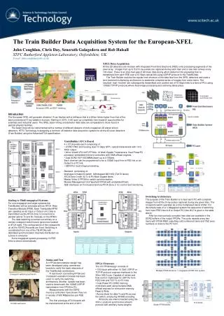
Diagnostics overview BC1 Bunch compressor SRF 1.3 GHz SRF 3.9 GHz TDS X&Y Diagnostic section Spectrometer Dump TOR toroid system for transmission measurements (1,3&4 for interlock) DC dark current monitors (upstream BC1, downstream BC1) BPM beam position monitor ~ 20 (not yet determined … every quad?) purpose: orbit correction, transfer measurements, dispersion correction OTR optical transition screen (with wire scanners WS?) • proposed beam line design: SRF 1.3GHz Standard diagnostics:
Diagnostics overview BC1 Bunch compressor SRF 1.3 GHz SRF 3.9 GHz TDS X&Y Diagnostic section Spectrometer Dump TDS transverse deflecting structure X & Y EO electro-optic longitudinal beam profile monitor -> B Schmidt BCM bunch compression monitors (CSR at D4 and CDR/CTR) SR synchrotron radiation monitor (energy and energy spread) BAM beam arrival time monitor • proposed beam line design: SRF 1.3GHz Special diagnostics:
Diagnostics overview BC1 Bunch compressor SRF 1.3 GHz SRF 3.9 GHz TDS X&Y Diagnostic section Spectrometer Dump COL collimators (1st & 2nd to remove dark current, 3nd & 4th for kicked e-) KIC fast kicker to off-axis screens (2 x and 2 y) Align laser for optics alignment BLM beam loss monitors (about 8-10 sufficient) • proposed beam line design: SRF 1.3GHz Additional devices:
Screen / Kicker arrangement (2) Horizontal slice emittance / vertical streak Vertical slice emittance / horizontal streak 45deg 76deg HK1 OTR1 OTR1 HK1 OTR2 OTR3 HK2 OTR4 OTR4 HK2 OTR6 OTR6 45deg 76deg VK1 OTR1 OTR2 VK1 OTR2 OTR3 VK2 OTR4 OTR4 VK2 OTR6 OTR5 3 cells = 11.4 m FODO lattice 6 off-axis OTR screens (y andx) Horizontal kicker Vertical kicker HK2 HK1 VK1 VK2 OTR1 OTR2 OTR3 OTR4 OTR5 OTR6 Bend plane of BCs defines the OTR arrangement
FODO lattice 3.8 m 10 modules 7.6 m 5 modules Diagnostic Section Engineering layout (3) BAM T1 CSR VK1 ABCM EOSD TDS-x TDS-y Alignment laser Lattice can be divided into modules: VK2 HK1 HK2 RES T2 Booster Linac SR 2.5m ABCM
Conclusions Conclusions (1): • For which bunch rep rate, 5MHz or 1MHz, shall the on-line slice emittance diagnostics be designed in BC1: • Desired resolution can easily be reached at 1 MHz but is just at the theoretical limit for 5 MHz. • Kickers with the required kick strength for 1MHz are in operation in several machines at DESY (‘off-the-shelf’). 5 MHz would requires new design and prototype development. • If standard FEL operation will be 5 MHz slice emittance diagnostics cannot be operated parasitically if designed for 1 MHz (or might not be used if resolution is not sufficient). • If standard FEL operation will be 1 MHz one would lose at least a factor of 1.6 in resolution if designed for 5 MHz
Conclusions Conclusions (2): Dump defines the horizontal streak direction in BC2. If the BCs are installed vertically slice emittance could be measured in the bend plane of BCs. Number of quads in current layout BC1 was 22 now 22 BC2 wsa 13 now 19 New lattice layout requires slightly more space BC1: 1.5 m in BC + 0.9 m in diag section = 2.4 m BC2: 1.0 m in BC + 1.5 m in diag section* = 2.5 m*Additional FODO cell for 45 deg lattice requires 7.6 m more space Layout of the dignostics sections can be arranged in modules. Components can be prealigned and tested. This saves time during installation and commissioning. Layout of BC1 diagnostic section almost finalized. After beam dynamic and sensitivity studies (2 months) the vacuum and engineering layout could be started
Coherentradiation • Status : • - spectrally resolving single shot instrument developed • (multi stage grating spectrograph with parallel read out) • Advanced prototype running at FLASH (THz beam-line) • Existence of spectroscopic fingerprints shown down to µm scale • To be done : • - develop compact monlithic version • explore and establish feedback capabilities • detailed planning of station lay-out existing detector unit Potential layout for 4-stage spectrograph
Electro-optical monitors • Status : • different methods under study at FLASH • integrity and validity of data largely explored • - spectral decoding method proven to be sufficiently simple • dedicated fiber-laser version under construction • To be done : • - step from ‘experiment’ to ‘on-line tool’ • more robust and reliable laser system (fiber-laser) • fast (parallel) read-out system (line camera) • direct (optical) coupling to optical timing system
Requirements / implications : • EO crystals inside beam pipe (r ~ 2-5 mm), retractable • optical ports for laser in/out ~0.6 m laser beam space underneath beam pipe : ~ 2 m2 optical table (laser +spectrometer + camera).
T. Wohlenberg: Bunch compressor section BC1 and BC2General remarks • Lengths of the vacuum system BC1 and BC2: • BC1: total length ~ 69m → chicane length ~ 27m → deflection of the chicane ~ 0.68m • BC2: total length ~ 90m → chicane length ~ 25m → deflection of the chicane ~ 0.33m • Vacuum requirements: • Pressure needs to be in the range of 10-10 mbar (next to cold sections) • Pump system: sputter ion pumps and titan sublimations pumps • Both sections are particle free : • The design of all vacuum components needs to be according to the particle free conditions. Early discussion of concept of all components including beam diagnostic is necessary! • All vacuum components have to be cleaned under particle free condition (clean room). • Installations needs to be done under local clean room conditions.
Bunch compressor section BC1 and BC2General remarks • From the point of view of vacuum technology both BC sections should be • treated similar. This should be valid for the aspect of material choice, • joining technology, support for the chambers etc.. • The design concept for the flat chamber in the chicane is similar to FLASH!
Bunch compressor section BC1 and BC2Schedule • Draft: • Components layout + girder and frames concept including electronics/diagnostics units concept ~ 1 year • Design of BC1 and BC2 ~1 year • Fabrication of all components ~ 1.5 years • 2007, A rough concept should be settled for the girders/frames concept including electronics and diagnostics as well as part of the layout of the components.→ layout for the arrangement of the components should be available! • 2008, The detailed concept for the layout of the components, electronic concept and the girder and frames concept should be finished.
Bunch compressor section BC1 and BC2open issues • Do we have the BC‘s chicane to be installed vertically or horizontally? → we prefer vertical installation! • Do all components need to be copper coated in both BC’s? • Can the RF-shielding remain the same as for FLASH or do we have to design a new concept for the flange connections, bellows, valves and pump connections? • Is a massive lead shielding necessary ? → need to be included into the girder and frame design! • How does the dump section for BC1 and BC2 look like? • What diagnostic installations will be needed next to the beam line?