UV-light
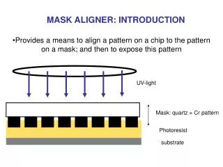
MASK ALIGNER: INTRODUCTION. Provides a means to align a pattern on a chip to the pattern on a mask; and then to expose this pattern. UV-light. Mask: quartz + Cr pattern. Photoresist. substrate. The aligner. Pump, service corridor. Lamp power supply. microscope. Manometer box.

UV-light
E N D
Presentation Transcript
MASK ALIGNER: INTRODUCTION • Provides a means to align a pattern on a chip to the pattern on a mask; and then to expose this pattern UV-light Mask: quartz + Cr pattern Photoresist substrate
The aligner Pump, service corridor Lamp power supply
microscope Manometer box Mirror house Sample holder Lamp house Mask holder Microscope Translation-control Alignment stage
Mercury lamp • g - line : 436 nm • h-line: 405 nm • i - line 365 nm S-1800 series are g-line photoresit
Mercury lamp • Life time: 600 h • Nitrogen cooling is very important. • Lamp must be cool before restarting … or you risk damaging the lamp. Therefore wait ~30 minutes after previous use. But it is better to leave the lamp on for several hours than turn off and on and off and on …. • The first exposure after turning on the lamp should be done with no wafer. • If the bulb explodes, it will fill the lithography area with toxic mercury vapor. This can cause severe neurological damage. EVACUATE THE LAB FOR AT LEAST 30 MIN. The mask aligner will also be seriously damaged. •
Mercury lamp power supply • It can be operated at constant power or constant Intensity • Constant intensity better reproducibility • CI1 refers to 365 nm • CI2 refers to 405 nm • In constant intensity mode, the controller monitors the lamp intensity measure on the feedback sensor and varies the power supplied to the lamp to keep the intensity selected • We work with CI2 because is the power meter we have. • I= 25mW/cm2
Lamp • Elipsoidal mirror • Cold mirror • Fly’s eyes lens • Condenser lens (32mm) • Frame for filters 7. Diffraction reducing lens plates (69 mm) 8. Turning mirror 9. Front lens UV-400 optics
Air pressure and nitrogen switches ON/OFF ON all the time
Travel limits: X: 3mm Y: 3mm : 3 ONLY MOVE THE THIN ENDS!!!!!
CONTACT ARM CONTACT-SEPARATION LEVER
MICROSCOPE • Fiber optic light pipe • Single field /splitfield shutter • Rotation for focus • Objective separation for splitfield operation • Iris diaphram • Objectives SPLITFIELD= left shutter fully clockwise; right shutter fully anticlockwise Left objective=left shutter half way; right shutter fully anticlockwise Right objective=left shutter fully clockwise; right shutter half way