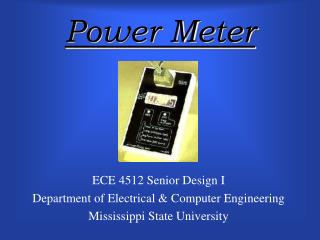
Power Meter
Power Meter. ECE 4512 Senior Design I Department of Electrical & Computer Engineering Mississippi State University. Team. A dvisor : Professor Raymond S. Winton T eam Leader : Wei-Keat Quek Contribution: A/D Converter, LCD Display, & Documentation T eam Members : Matthew Hemphill

Power Meter
E N D
Presentation Transcript
Power Meter ECE 4512 Senior Design I Department of Electrical & Computer Engineering Mississippi State University
Team Advisor: Professor Raymond S. Winton Team Leader: Wei-Keat Quek Contribution:A/D Converter, LCD Display, & Documentation Team Members: Matthew Hemphill Contribution:Voltage-sensing circuit & Documentation Scott Fredrick Contribution: Current-sensing circuit & Documentation James Nixon Contribution: Microcontroller & Documentation
Motivation To provide average American householders with a portable & accurate digital power meter • Importance • Can educate consumers, save them money, & aid in purchase decisions • Can aid in troubleshooting problem circuits & in making decisions to conserve energy • Relevance • Allows for concrete, practical design experience based on curriculum • Allows for group collaboration and division of tasks based on each member’s specialty
Problem Statement • To accurately sense the voltage and current used over a range of typical household devices. • To achieve reliable power measurements by taking phase differences between the voltage and current, i.e. the power factor, into account.
Design Requirements • Voltage-sensing circuit (0 to 120 Vrms) • Current-sensing circuit (0 to 30 A) • Power Factor Calculation (DS87Cx20 Microcontroller) • Power (9 V Battery)
Design Requirements • Display (4-digit LCD) • Power Measurement Range (0 to 3600 W) • Energy Measurement Range (0 to 86.4 kWhrs) • Tolerance (+/- 3%) • Size & Packaging (Plastic enclosure – 4” x 8” x 1.5” (W x L x D))
Voltage-Sensing Circuit vo = (1 + 2*R4/R3)(v2 – v1) where = R2/R1
Power Factor Calculation Sampling & Displacement • Sampling rate >= 1/(8*fo) where fo = 60 Hz • Displacement = -/ where = 2f Example • = * displacement = 2(60 Hz)*1.5 ms = 0.565 rad/s Power • P = Vrms*Irms*cos() = (127.6 V)/(68.714 mA)(0.8446) = 7.4 W Maclaurin Series • cos() = 1 - ^2/2! + ^4/4! - ^6/6! + … + (-1)^k ^2k/2k! + … C Code • After the first three harmonics, cos () = cos(0.565) = 0.8446.
C Program Flow Select function Pinstantaneous Start Calculate real power Pavg Input time Time out or disconnect? No Receive digital voltage value (Reference) Receive digital current value Yes Display output End Has first zero-crossing been reached? No Yes Calculate displacement between current and voltage
UMPS Simulation Vcc Vcc 2 3 4 6 7-14 5/1 10 K 7 8 10-17 22 31 DS87Cx20 23 30 pF 40 19 SW2 0.1 F SW1 4 MHz 20 18 30 pF
UMPS Simulation c:\temp\lcd.asm org 0 ajmp Main org 020h ; Program Main Main: mov CKCON,#%00001000 ; Use Internal /4 Clock for Timer0 mov TMOD,#%00000001 ; Timer0 - Uses Internal Clock ; - Run in Mode 1 mov TCON,#%00010000 ; Start Timer0 running mov IE,#%10000010 ; Enable the Timer 0 Interrupt ; LCD Display mov P1,#03Fh ; Make sure all LCD lines are Low acall Dlay5 ; Wait 15 ms for the Display to Power Up acall Dlay5 acall Dlay5 mov P3,#$7 ; Output a 7 on the Display Line clr P1.6 ; Clear the RS Line setb P1.7 ; Toggle the LCD "E" Clock clr P1.7 acall Dlay5 ; Wait 5 ms for the instruction to execute : CPU Registers SP 07 P1 0000003F P3 00000007 Resources 7 SW1 SW2
Conclusions/Future Work Conclusions • Ensure our tolerance levels are met • Meet challenge of accuracy Future Improvements • Expand functions for both AC & DC measurements • Expand measuring range • Improve tolerance levels • Allow PC connectivity • Improve internal power consumption
References [1] “ADC 0801/ADC 0802 ADC 0803 ADC 0804 ADC 0805 8 bit µP Compatible A/D Converters”, National Semiconductor Corporation, U.S.A., 2000. [2] “EDC190 4-Digit 7-Segment Liquid Crystal Display”, Microelectronic Company, U.S.A., June 1987. [3] Fisher, G. J., “An Enhanced Power Meter for SPICE2 Circuit Simulation,” IEEE Transactions On Computer-Aided Design, Harris Semiconductor, Melbourne, FL, May, 1998. [4] Garverick, S. L., McGrath, D. T., Baetsch, R. D., and Fujino, K., “A Programmable Mixed-Signal ASIC for Power Metering,” IEEE International Solid-State Circuits Conference, GE Corporate Research and Development, Schenectady, NY,January, 1991. [5] Graf, Rudolf F., Encyclopedia of Electronic Circuits, Vol. 3, TAB Books Inc., 1991. [6] Hanselman, Duane, and Littlefield, Bruce, Mastering MATLAB: A Comprehensive Tutorial and Reference, The MATLAB Curriculum Series, Upper Saddle River, NJ: Prentice Hall, 1996. [7] Hayes, Thomas C., and Horowitz, Paul, Student Manual for the Art of Electronics, Cambridge University Press, 1989. [8] Helps, Richard, “Op-amps Note,” http://www.et.byu.edu/~rhelps/EET444/html/op-amps_note.htm (11/9/00). [9] "High-Speed Microcontroller User Guide", Dallas Semiconductor, http://www.dalsemi.com/ (10/10/00).
References (cont.) [10] Horowitz, Paul, and Hill, Winfield, The Art of Electronics, 2nd ed. Cambridge University Press, 1989. [11] Lamego, M. M., Sousa, G. C. D., and Vierira, J. L. F., “A Single Phase Microcontroller Based Energy Meter,” IEEE Instrum. And Meas. Tech. Conf.Proc., Electrical Engineering Dept., Universidade Federal do Espirito Santo, May, 1998. [12] Landee, Robert W., and Davis, Donavan C., Electronics Designer’s Handbook, 2nd ed. New York: McGraw-Hill, 1977. [13] Lapuh, R., Visocnik, I., and Arnsek, A., “Single DVM Sampling Power Meter For Low Frequencies,” IEEE Instrum. And Meas. Tech. Conf. Proc., Slovenian Institute of Quality and Metrology, Ljubljana, Slovenia, May 2000. [14] Lenk, John D., Circuit Encyclopedia & Troubleshooting Guide, Vols. 1 & 2, New York: McGraw-Hill, 1974. [15] Liu, L. X., Chen, T. P., and Chua, S. W., “Influence of Frequency Difference between Current and Voltage on AC Power Measurement Result,” National Measurement Centre of Singapore Productivity and Standards Board, Singapore, 2000. [16] May, R., “A PIC Based AC Power Meter,” www.edtn.com/embapps/emba027.htm, July, 1998. [17] Neamen, Donald A., Electronic Circuit Analysis and Design, Boston, MA: WCB McGraw-Hill, 1996. [18] Predko, Myke, Handbook of Microcontrollers, New York: McGraw-Hill, 1999.
References (cont.) [19] Svensson, S., “Preferred Methods for Power-Related Measurements,” 8th International Conference on Harmonics and Quality of Power ICHQP ’98, Swedish National Testing and Research Institute, Boras, Sweden, October 1998. [20] Tuinenga, Paul W., Spice: A Guide to Circuit Simulation & Analysis Using PSpice, 3rd ed. Englewood Cliffs, NJ: Prentice Hall, 1995. [21] Voland, Gerald, Engineering by Design, Reading, MA: Addison-Wesley, 1999. [22] Woodward, W. S., “Optical isolator computes watts,” Electronic Design, 102-103, October 14, 1994. [23] Ziemer, R., Tranter, W., and Fannin, D., Signals and Systems: Continuous and Discrete, 4th ed. Upper Saddle River, NJ: Prentice Hall, 1998.