Power, Voltage, and Current Meter
Power, Voltage, and Current Meter. Pim Shih Eric Wild Professor: Gary Swenson T.A. Julio Urbina University of Illinois at Urbana Champaign Department of Electrical and Computer Engineering. Power Voltage and Current Meter. Project Goals.

Power, Voltage, and Current Meter
E N D
Presentation Transcript
Power, Voltage, and Current Meter Pim Shih Eric Wild Professor: Gary Swenson T.A. Julio Urbina University of Illinois at Urbana Champaign Department of Electrical and Computer Engineering
Project Goals • Build a power supply able to display voltage, current, and power. • The device will be used as an educational tool for students in early stages of studies. • Device is upgradeable to be used in various applications. • Device is inexpensive and marketable.
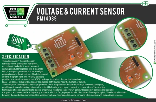
Description • Power Supply • 0-9V DC • Voltage is varied using potentiometer • AA004-02 Magnetic Field Sensor • Measures the magnetic field • MC68HC705P6 Microprocessor • Converts the analog signal to a digital signal • Sends signal to an LCD after programming
Hardware • Power Supply • 0 to 9 volt DC power supply • LCD display • DMC Series LCD • Displays voltage, current, and power generated by the power supply
Hardware (cont.) • Voltage Regulator • MC7800 series • Constant 5 volts is supplied to the Magnetic field sensor, Op-amp, Micro-Controller, and LCD display • Op-amp • Amplifies signal from the field sensor to readable levels for the micro-controller
Hardware (cont.) • The MC68HC705P6 Microcontroller • Most important part of the project • Converts the voltage and current to ASCII characters • Outputs ASCII characters to an LCD display
Power Supply • Transformer • Transforms 120 Volts AC down to 9 volts AC • Rectification • Converts AC to DC using diodes and capacitors • Filtering • Smoothes out pulsating DC to just DC using capacitors • Voltage Regulation • Used Voltage Regulator ICs to keep voltages constant and steady across loads
Power Supply (cont.) • Variable DC Voltages • Between 0-9 volts • Switched between using potentiometer • Implemented using a resistor/transistor array • Output Isolation and Stability • Diodes used for isolation of outputs • Capacitors ensure low-noise voltage outputs
GMR Magnetic Field Sensor • General Comments • Designed to measure or sense magnetic filed strength over a wide range of fields • Designed to directly detect magnetic field rather than rate of change in magnetic field • Very sensitive to small changes in magnetic field • Magnetic fields produced by current carrying devices makes it usable as current sensors
Axis of sensitivity Chip GMR Magnetic Field Sensor (cont.) • Current measurement concepts • Below illustrates the sensor package orientation for detecting the field from a current carrying wire. • This application allows for current measurement without breaking or interfering with the circuit of interest. • Note: wire can be located above or below chip as long as it is oriented perpendicular to the sensitive axis
M68HC05 Microcontroller • Definition • A microcontroller is a very small product that contains many of the functions found in a computer system • A microcontroller is packaged as a single chip that can be programmed by the user with a series of instructions loaded into its memory
M68HC05 Microcontroller (cont.) • Hardware features • HCMOS technology • 8-bit architecture • Internal 16 bit timer • 2.1 MHz internal operating frequency, 5 volts; 1.0 MHz, 3 volts • Serial Communications Interface System • Serial Peripheral Interface System
M68HC05 Microcontroller (cont.) • Software Features • Upward Software Compatible • Efficient Instruction set • Memory Mapped I/O • On –Chip Memory • 176-304 bytes of random access memory • 240 bytes of read only memory • 7600 to 7744 bytes of programmable memory
Microcontroller Procedure • Voltage measurement • Done by sending the output of the power supply to a pin on the microcontroller • Current measurement • Output of power supply is sent through a transducer which transformed current into voltage • Power measurement • Used multiply command in the microcontroller
Coding Procedure • Algorithm to display voltage: 1)Set Port C, Bit 2 to output 2)Loop forever 3)Set RC oscillator 4)Turn on Analog to Digital converter 5)Check ready flag 6)Toggle Enable
Original Design • Differences on original design • Used resistors instead of potentiometers to calibrate the magnetic field sensor • Used V=IR instead of magnetic field sensor to measure current • Used less number of capacitors to reduce voltage ripple
Performance Requirements • Requirements • The accuracy of the current, voltage, and power meter will be accurate to within five percent of the actual value. • This is due to the fact that the LCD display is 2 X 16. Which means there are two lines each holding 16 characters. • Values will be in milliamps to make values as accurate as possible
Tests Performed: • Tested load voltage, and current using different values of load resistances. • Tested the effects of temperature, and air flow on circuit. • Tested outside interference.
Problems and Challenges • Outside Interference • Outside magnetic field interfered with magnetic field sensor reading on breadboard • Noise due to wires – inductance/capacitance EM noise • Capacitors • Original number of capacitors did not reduce voltage ripple to desirable levels • Resistors • Load resistor too small • Clock • Clock signal must be placed very close to the micro-controller, otherwise circuit does not work
Successes • Successfully implemented a power supply, magnetic field sensor, and a microprocessor to LCD • Improved project over time while overcoming original design problems and challenges • Attained an efficient and accurate working device as proposed • Attained a very high quality device with practical purposes while keeping costs low • Learned a great deal through this project
Competitive Analysis • Competitors Agilent Technologies, Fluke, Philips, Tektronix, many others • Strengths • Affordable, portable, easy to use, easily upgradable • Weaknesses • Limited but ample functionality
Parts Cost • For Main Power Supply Quantity Cost 1)117-9 Volt (100 mA) transformer 1 $3.00 2)Switch, SPST 1 $1.12 3)AC Line Cord 1 $2.00 4)Diodes – 1N914 Diode 4 $0.22 5)LED 1 $0.10 6)Resistors – 100 – 100 K ohms 5 $0.05 7)10 Kohm Potentiometer 1 $0.49 8)Capacitors –1 microfarad –1 nanofarad/16V 5 $0.50 9)Transistors 3 $0.26 10)Three Terminal Positive Fixed Voltage Reg. 1 $1.60 Total for main power supply: $10.96
Parts Cost (cont.) • For Current Measurement Quantity Cost 1)AA004-02 – Magnetic Field Sensor 1 $11.00 2)U1 – LM324 Low Power Quad op-amp 1 $3.00 3)Resistors 100 ohm – 1 Mohm 8 $0.05 4)R8, R12 – 1 Mohm 2 $0.05 5)Capacitors 2 $0.10 Total Cost for Current Measurement: $14.70
Parts Cost (cont.) • For Micro-chip to LCD Quantity Cost 1)MC68HC705P6 – Micro-controller 1 $8.50 2)16 pin Display Connector/to display 1 $5.05 3)Resistors 15 ohm-4.7 Mohm 1 $0.05 4)Capacitors – 0.1 microfarad, 27 Pico farad 2 $0.10 5)Oscillator – 4 MHz 1 $1.59 Total Cost for Micro-Chip to LCD: $15.39
Total Cost • Total cost of entire project (total of three plus breadboard) = $46.05 (estimate) • Total cost = Labor + Parts =$50/hour*2.5*120*2+$46.05 = $30,046.05
Potential Improvements • Ways to gain stability • Placing shields around chips and magnetic sensor to decrease outside magnetic field • Design a different setup of amplifier configuration using feedback loops to give up gain for stability • Use a different op-amp configuration to decrease temperature dependence
Potential Markets • Educators • Labs • Software could be reconfigured to be used in many applications.
Conclusions: • Great tool for engineering college students • Flexible design