Overview of Frequency Scanning Interferometry (FSI) and Its Applications in Applied Geodesy
270 likes | 394 Vues
This document presents a detailed overview of Frequency Scanning Interferometry (FSI), focusing on its concept, implementation, and results in length measurement with high precision. Originally developed for online alignment of the ATLAS SCT tracker, FSI achieves 1mm precision over 5m through advanced techniques such as thermal drift cancellation and amplitude modulation. Key developments include the use of dual laser systems and software phase extraction for accurate signal processing. This exploration emphasizes the significance of FSI in modern applied geodesy and its versatile applications.

Overview of Frequency Scanning Interferometry (FSI) and Its Applications in Applied Geodesy
E N D
Presentation Transcript
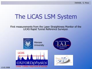
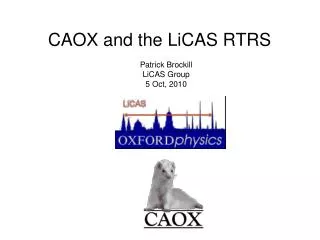
LiCAS Project: FSI Overview Richard Bingham, Edward Botcherby, Paul Coe, John Green, Grzegorz Grzelak, Ankush Mitra, John Nixon, Armin Reichold University of Oxford Andreas Herty, Wolfgang Liebl, Johannes Prenting, Markus Schloesser Applied Geodesy Group, DESY
Contents • FSI Concept • ATLAS FSI • Implementation • Results • LiCAS Extensions FSI Overview
IRef time Change of phase: DFRef IGLI time Frequency Scanning Interferometry • Interferometric length measurement technique • Require precision of 1mm over 5m • Originally developed for online alignment of the ATLAS SCT tracker Tunable Laser Reference Interferometer: L Measurement Interferometer: D (Grid Line Interferometer (GLI)) Change of phase: DFGLI FSI Overview
FSI: Length Measurement DFGLI DFRef FSI Overview
FSI: Thermal Drift Cancellation • Thermal effects add subtle systematic errors to FSI • Nanometre movements can contribute micron errors (µ (n/Dn) ) • Use two lasers tuning in opposite directions to cancel thermal drift FSI Overview
FSI: Thermal Drift Cancellation DFGLI DQ(+) True Gradient DQ(-) Measured Gradient with Laser Tuning Up Measured Gradient with Laser Tuning Down DFRef FSI Overview
FSI: 2-Laser Thermal Drift Cancellation FSI Overview
FSI: ATLAS Implementation FSI Overview
6 simultaneous length measurements made between four corners of the square. +7th interferometer to measure stage position. Displacements of one corner of the square can then be reconstructed. FSI: ATLAS Test Grid FSI Overview
FSI: ATLAS Resolution FSI Overview
1mm FSI: ATLAS Resolution • Stage is kept stationary • RMS 3D Scatter < 1 mm FSI Overview
Amplitude Modulation @ f1 C-Band Amplifier (1520-1570 nm) f1 L-Band Amplifier (1572-1630 nm) f2 Amplitude Modulation @ f2 APD Demodulator @ f1 , F1 Demodulator @ fn , Fn ADC +AMPS RAM Detectors Demodulator @ f2 , F2 Retro Reflector To PC LiCAS FSI System ATLAS FSI System Laser 1 Laser 2 Reference Interferometer Splitter Tree piezo detector Uncollimated Quill Collimated Quill 1m GLI 5m GLI FSI Overview
l2 wavelength l1 time Amplitude Modulation @ f1 f1 Volts Demodulator @ f1 , F1 f2 Amplitude Modulation @ f2 l2 time wavelength Demodulator @ f2 , F1 Volts l0 time time Two Laser AM Demodulation • Need 2 lasers for drift cancellation • Have both lasers present & use AM demodulation to electronically separate signals M1 t0 t1 M2 Laser 1 Laser 2 Detector t0 t1 FSI Overview
Two Laser AM Demodulation 15% mod. Volts 15% mod. Time Volts Time • Amplitude Modulation on FSI fringe • @ 40 & 80 kHz (now) 0.5 & 1MHz (later) • High Pass Filter • FSI fringe stored as amplitude on • Carrier (àla AM radio) • Demodulation reproduces FSI Fringes FSI Overview
Results of Demodulation Both signals have same frequency !! Demodulation of modulated laser does not effect interferometer signal FSI Overview
Carré Algorithm Reference Interferometer Phase Extraction • Reference Interferometer is FSI’s “yard-stick” • Must measure interferometer phase precisely • Uses standard technique of Phase-Stepping Step1: I(ftrue-1.5Df) Step2: I(ftrue-0.5Df) Step3: I(ftrue+0.5Df) Step4: I(ftrue+1.5Df) Reference Interferometer mirror moved in 4 equal sized steps ftrue FSI Overview
Raw Data Reconstructed Interferometer Signal Software Phase Extraction • Telecoms laser tunes linearly • Extract phase with software “phase-stepping” FSI Overview
FSI Challenges for LiCAS • Telecoms wavelength (1520nm – 1640nm) • Cheap, high quality tuneable lasers • 120nm (15THz) continuous tuning range • 40nm/s (5THz/s) continuous tuning speed • Use Erbium Doped Fibre Amplifiers • Output power between 4mW and 125mW • Reduced cost • Increased flexibility and reusability FSI Overview
g g Incoming Single Photon g Outgoing Photons Erbium Doped Fibre Amplifiers • EDFA are optical power amplifiers • Used to amplify low power tunable laser • Standard equipment for Telecoms • but will it work for FSI ? 4I11/2 Pump 980nm Decay Single Telecoms Channel 4I13/2 Signal ~1550nm fluorescence 4I15/2 1610 Wavelength / nm 1530 FSI Overview
EDFA System FSI Overview
Fibre end Collimation lens Retroreflector Quill Collimation • Refractive • Reflective Fibre Retroreflector Reflective, off-axis paraboloid FSI Overview
Commercial Collimation FSI Overview
Fibre Retro Custom Collimation • 0.8% Return for on-axis Retro • 0.04% return for 7mm off axis retro FSI Overview
Reference Interferometer 1 • Michelson style interferometer Beam Splitter Photodetector Long Arm Short Arm FSI Overview
Reference Interferometer 2 • GLI Style interferometer Retroreflector Collimatior FSI Overview
Summary • FSI provides abosoluted length measurements • Multiple laser system using amplitude modulation • Software phase extraction • Telecommunications wavelengths: cheap, high quality equipment • Erbium Doped Fibre Amplifiers provide scalable power output • Collimation optics used for longest distance FSI Overview