CARBON DIOXIDE CAPTURE
CARBON DIOXIDE CAPTURE. Ferize VAHABOVA 20900917. GREENHOUSE EFFECT. GREENHOUSE GASES. GLOBAL CO2 EMISSION BY SOURCE. Photo Source: Carbon Dioxide Information Analysis Center. GLOBAL CO2 EMISSION BY SOURCE. Photo Source: Carbon Dioxide Information Analysis Center.

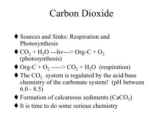
CARBON DIOXIDE CAPTURE
E N D
Presentation Transcript
CARBON DIOXIDE CAPTURE Ferize VAHABOVA 20900917
GLOBAL CO2 EMISSION BY SOURCE Photo Source: Carbon Dioxide Information Analysis Center
GLOBAL CO2 EMISSION BY SOURCE Photo Source: Carbon Dioxide Information Analysis Center
GLOBAL CO2 EMISSION BY COUNTRY PhotoSource: EDGAR 4.2FT2010 (JRC/PBL, 2012); BP, 2013; NBS China, 2013; USGS, 2013; WSA, 2013; NOAA, 2012
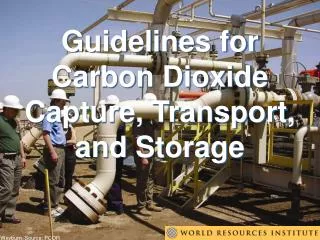
CARBON CAPTURE AND SEQUESTRATIONIS… … a three-step process that includes:
CARBON CAPTURE AND SEQUESTRATION Photo Source: Cooperative Research Centre for Greenhouse Gas Technologies.
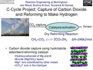
PRE – COMBUSTIONMETHOD • Pre-combustion capture is applicable to integrated gasification combined cycle (IGCC) power plants, where solid fuel is converted into gaseous components ("syngas") by applying heat under pressure in the presence of steam and oxygen. • Capture of the CO2 is currently accomplished an acid gas removal (AGR) process of absorption in a solvent. Photo Source: Global CCS Institute Co2 Capture Technologies Pre-Combustion Capture, January - 2012
ADVANTAGE/DISADVANTAGE ADVANTAGES DISADVANTAGES Pre-combustion is only applicable for new power plants because the capture process has to be an integrated part of the combustion process. Pre-combustion technologies like IGCC are not as mature as post-combustion capture technologies. Gas turbines running on hydrogen are a huge challenge. Synthesis gas is: • Concentrated in CO2 • High pressure Resulting in: • High CO2 partial pressure • Increased driving force for separation • More technologies available for separation • Potential for reduction in compression costs/loads
POST COMBUSTION METHOD • Post-combustion capture is primarily applicable to fossil fuel based systems such as conventional pulverized coal (PC)-fired power plants, where the fuel is burned with air in a boiler to produce steam that drives a turbine/generator to produce electricity. Photo Source: Bellona Environmental CCS Team
ADVANTAGE/DISADVANTAGE ADVANTAGE DISADVANTAGE Amine processes are commercially available at relatively small scale and considerable re-engineering and scale-up is needed Power Loss Most sorbents need very pure flue gas to minimize sorbent usage and cost. Steam extraction for solvent regeneration reduces flow to low-pressure turbine with significant operational impact on its efficiency and turn down capability. Water use is increased significantly with the addition of PCC particularly for water cooled plants. • Can be retrofitted to existing plants • It enables the continued deployment of the well established Pulverized Coal (PC) technology familiar to power industries worldwide • The continued development of improved materials for Ultra Supercritical (USC) plants will increase the efficiency and reduce the CO2 emissions of future PC plants • The widespread R&D on improved sorbents and capture equipment should reduce the energy penalty of PCC capture.
OXYFUEL COMBUSTION • In traditional fossil fuelled power plants combustion is carried out by using air, with the nitrogen (N2) in the air following the flue gas. An alternative is to use pure oxygen (O2) instead of air in the combustion. • The advantage of this so-called oxyfuel technique is that the flue gas contains only steam and CO2. These two components are easily separated through cooling, by which the water then condenses and a CO2 rich gas-stream is formed. • The currently available technologies for pure oxygen-production are based primarily on cryogenic separation of air. Here the air is cooled down below the boiling point before the liquefied oxygen, nitrogen and argon are separated. However, the high amount of energy involved in this process make it a very expensive process. Promising on-going research to develop membranes that separate oxygen from air may drastically improve efficiently and lower capital investment costs.
OXYFUEL COMBUSTION FLOWCHART Photo Source: Global CCS Institute Co2 Capture Technologies Oxyfuel Combustion Capture, January - 2012
ADVANTAGE/DISADVANTAGE ADVANTAGE DISADVANTAGE It is not possible to develop sub-scale oxy-combustion technology at existing power plants. The combustion of fossil fuels and pure oxygen creates high material stress, hence the development of new materials is a prerequisite for deployment of this technology. It is expensive to produce pure oxygen, and research activities are ongoing worldwide to find new ways to produce oxygen. • No chemical operations or significant on-site chemical inventory. • Up to 100 percent CO2 can be captured through this process. • The best information available today (with the technology available today) is that oxy-combustion with CO2 capture should be at least competitive with pre- and post-combustion CO2 capture and may have a slight cost advantage.
MEMBRANES • Membranes can be used for separating CO2 from other gas components. The technology is available today but will take some years and further research before it may be available for large-scale CO2 capture at generation plant. Photo Source: Bellona Environmental CCS Team
CHEMICAL LOOPING • Chemical looping is a new technology for combustion with inherent CO2 capture. It is a significant departure from traditional combustion methods. It is flameless combustion technology combining two reactors, one air reactor and one fuel reactor. Photo Source: Bellona Environmental CCS Team
INTEGRATED FUEL CELLS • Integrated fuel cells enable production of the clean energy carriers electricity and hydrogen from fossil fuel or bio-fuel with ultra-high efficiency and integrated CO2capture. Photo Source: Bellona Environmental CCS Team
ADSORPTION • CO2 capture by adsorption is not yet a mature commercial technology, but is currently being tested at a laboratory scale. Research programs are underway with advances in the technological expected, paving the way for adsorption as a future solution for CO2 capture. Photo Source: The Cooperative Research Centre for Greenhouse Gas Technologies
POST-COMBUSTION CO2 CAPTURE AND STORAGE, BRINDISI, ITALY. Photo Source: Enel Group
POST-COMBUSTION CO2 CAPTURE PILOT PLANT, PUERTOLLANO, SPAIN. Photo Source: ELCOGAS S.A. IGCC Power Plant
OXYFUEL PILOT PLANT, SPREMBERG, GERMANY. Photo Source: Vattenfall AB
CARBON EMISSION IN TURKEY Data Source: TurkiyeIstatistikKurumu
CARBON CAPTURE AND SEQUESTRATION IN TURKEY • In 2009, a project named “Türkiye'de Termik Santrallar ve Sanayi Tesislerinden Gelen Karbondioksit Emisyonu Envanterinin Çıkartılması ve Karbondioksitin Yeraltı Jeolojik Ortamlarda Depolanma Potansiyelinin Belirlenmesi” was held by ORTA DOĞU TEKNİK ÜNİVERSİTESİ PETROL ARAŞTIRMA MERKEZİ (ODTÜ PAL)and TÜRKİYE PETROLLERİ ANONİM ORTAKLIĞI (TPAO) • The aim of this project was to determine the suitable places in Turkey for CO2 storage and to investigate the details of the project and make its economical analysis.
SEVERAL PLANTS WITH CCS PROJECTS FROM DIFFERENT CONTINENTS Data Source: Bellona Environmental CCS Team
REFERENCES • http://www.epa.gov • http://energy.gov • http://www.globalccsinstitute.com • http://cdiac.ornl.gov • http://www.eie.gov.tr • http://www.tuik.gov.tr • http://www.enel.com • http://www.elcogas.es • http://corporate.vattenfall.com