Closed Loop Gas System
Closed Loop Gas System . B.Satyanarayana for S.D.Kalmani TIFR, Mumbai. Status of Closed Loop gas system and some results. What is Closed loop system ?

Closed Loop Gas System
E N D
Presentation Transcript
Closed Loop Gas System B.Satyanarayana for S.D.Kalmani TIFR, Mumbai
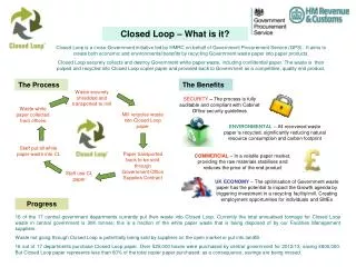
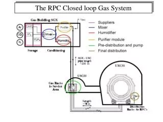
Status of Closed Loop gas system and some results What is Closed loop system ? The basic function of the gas system is to mix the gas components in the appropriate proportion, to distribute the mixture to the individual chambers as well as to purify and recycle the used gas. The large detector volume and the relatively expensive gases make a Closed Loop System mandatory. It is observed that, the performance of RPC largely depends on the quality of the gas mixture used. The current drawn by the chambers increases with poor quality of gas mixture. So, it is very important to assure a good quality of gas in the RPC system.
Purpose and motivation • ICAL RPCs Will be operated using non–flammable gas mixture of C2H2F4-iC4H10-SF6, which is relatively expensive. Based on economics and due to the large system size (~30K RPCs), RPCs are operated in re-circulating (90-95%) closed-loop system. • The current drawn by the chambers can rapidly rise if the amount of pollutants in the mixture increase, be due to poor gas quality at the source (e.g. polluted Freon bottles), the accumulation of impurities due to malfunctioning or saturated gas purifiers, leaks in the gas system or detectors, etc. • The goal is finding the operational conditions that will keep the RPC gas purity near the level of the fresh gas quality to ensure proper operation of the large RPC systems. • Total number of RPCs in the ICAL = 3 x150 x 64 = 28,800 • Total gas volume = 28,800 x 195cm x 191cm x 0.2cm = 214,531 litres
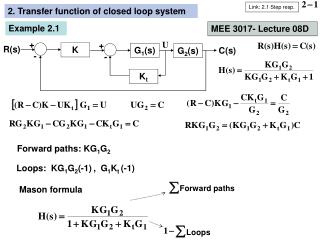
Line diagram of the close loop gas recirculation and purification system PT 2 Displacers Molecular Sieves Molecular Sieves Pneumatic Cylinders Radical Remover Low pressure High pressure Diaphragm Pump PT 1 Gas purifiers Exhaust Receiver tank inlet PT 3 MFC 5 Hygrometer N2 input Non-return valve Bypass Feeder valve Vacuum Pump Storage Tank Outlet PT 6 1 2 3 4 PT 5 RPC stack (this part is outside the gas unit cabinet) Exhaust Mass flow controllers MFC 1,2,3,4 PT 4 • Gas Mixing (On-line) • Gas Recirculation • Gas Purification system • Control System (PLC) MFC 6 Low pressure regulator
Gas purification process Gas mixture quality: Presence of impurities in the return gas from the RPCs Possible worsening of RPC performance due to impurities Removal of water vapour by combination of 3A and 5A molecular sieves continuous duty purifier. Removal of oil vapours by 3X molecular sieves Removal of radicals (F-, HF etc.) by disposable activated Alumina Removal of Oxygen by CuZn and Ni-NiO on activated Alumina/Silica by continuous duty purifier using standard cartridges Final goal was to achieve the moisture and Oxygen levels to less than 2 ppm
Basic Components Moisture sensor, Pan metrics Oxygen sensor, GE sensing Siemens PLC Sequence controller Completely Automated Some Parameters Auto-refill starts at 1.150bar (set value) Filled pressure (Pt5) is 1.450 bar (set value) Manual refill after evacuation (Fast refilling) Provision for exhaust through a MFC (#5)
MIXING UNIT This system will have dual supply of mixed gas. One for fast filling of the gas in the closed loop system say about 90LPM to fillthe gas in the loop, which is about 180Liters. Second one with 50 to 100 SCCMto replenish the exhaust gas which will be on-line.
Some pictures of close loop gas system Rear Front
Design parameters of the pilot system RPCs (12) 8litres x 12 = 96litres +20litres (main cylinder) +20litres (buffer cylinder) Total Gas in the close loop system ~180litres If filled at 10/20SCCM will take1000 hours. So high filling rate of say 15litres/min 10Hours is required. Loop flow = 1litre per minute (80cc/RPC) and top up = 10cc Positive pressure to be maintained for smooth gas flow through RPCs (1.006 bar to 1.009 bar, i.e. 3mbar difference). Lab pressure changes between 1.004bar to 1.010bar twice a day. Auto-refill starts at 1.150bar (set value) Filled pressure (PT5) is 1.450 bar (set value) Manual refill after evacuation (Fast refilling) Provision for exhaust through MFC5
Performance of close loop system • Depends on maintaining pressure balance, flow rate and efficiency of purification process. • Depends very much on the leak integrity of RPC. • Both factors must be carefully addressed to achieve good efficiency of close loop recirculation. • Operates at very low pressure difference. Typically 10 to 20mmWC. Hence the system is sensitive to changes in the ambient room pressure. • Removal of Contaminations: Air, Water vapour along with air and break down radicals specially of SF6
We have 3 channels connected to the CLS system as follows : Ch #1 :RPC tray has Four (1 Meter X 1 Meter) RPC's in the tray as shown below. CH #2 : RPC with 2M X 2M in a tray (AL 11) CH #3 : RPC with 2M X 2M in a tray (AL 15) So we have equivalent 3 RPC's (2M X 2M ) in the CLS NOTE : Pressure drop seen is ~2mmwater column (between input and output)
Day to Day: monitoring parameters :PT5 Supply Pressure and PT1 :Suction pressure Filled pressure (PT5) is 1.450 bar (set value) Auto-refill starts at 1.150bar (set value)
MONSOON EFFECT: Problem encountered due to variation in room pressures: Multiple Auto-refilling of gas! Bubbles were bubbling due to high pressure inside RPC
Need for modification: Software and Hardware • The RPC pressure will track PT6 which is the room pressure and maintain it above room pressure by a difference delta which is presently 2mBar (20mm of water column). • System can operate in 2 modes for operation settings : • we can operate the system in in • previous settings or • modified settings • a. Old Absolute Mode : Set points PT1 are named as SP1 Abs and SP2 Abs • b. SP1 Diff and SP2 Diff for setting for upper and lower set points for PT1 respectively. • c. K2 (0.0995) lowermost limit for PT1 and K2 (=1.008) for upper most for PT1 ====Range of pressure at which the System operate.
Drastic variation in pressure during Mumbai monsoon Hence the need for correction System pressure/RPC pressure i.e. PT1 follows the PT6 (Room pressure)
When the system pressure is high, the MFC6 flow is reduced, from 11.8 SCCMto 9.5 SCCM or vice versa
AUTO REFILL LOOKS TO BE REASONABLE : BUT MFC6 FLOW has reduced to almost 2 SCCM (very low)
CONCLUSION : Closed Loop System is functioning well as per the design, need to add more RPC’s in the loop. On-line RGA is frequently done to qualify the quality of gas. BUT need to do more analysis in detail for any breakdown radicals. We need to fine tune the system to regulate the gas flow (through MFC6) as the DATA for room pressure variation for one full monsoon season is available with us.