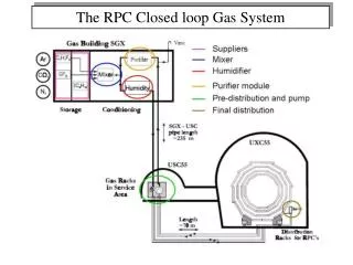
The RPC Closed loop Gas System
The RPC Closed loop Gas System. Schedule for completion - update. Status Supplier: ok Mixer: ok Humidifier: ok Purifiers: installed, but not completely commissioned Pre-distribution and pump: ok Final distribution: ok (minor detail to fix)

The RPC Closed loop Gas System
E N D
Presentation Transcript
Schedule for completion - update Status Supplier: ok Mixer: ok Humidifier: ok Purifiers: installed, but not completely commissioned Pre-distribution and pump: ok Final distribution: ok (minor detail to fix) Pressure Transmitter on the detector: few sensors are missing
Commissioning strategy Phase 0: leak test Leak test of the main pipes form SG to USC and from USC and UXC. Phase 1: debug of circuit In all racks, the two supply lines for the upper half-wheel and the bottom half-wheel are swapped. Same for the return line. Problem fixed for W+2 and W+1 (the pipe is flexible). For RE+1, RE+2, RE+3 the pipe are rigid and CRIOTEC will fix the problem this week. Also warn to CRIOTEC to avoid the same problem for the negative wheels and endcaps. Flushed for few days with argon the gas distribution racks for W+2, W+1. First check of the flow-cell calibration done.
Commissioning strategy • Phase 2: debug gas rack distribution • System (up to purifiers, purifiers excluded) flushed with R134a and run in closed loop mode to check both the full system and the flow-cell calibration. At the moment only W+1 rack under test (W+2 and W0 in the the Global Run). • As soon as the gas connection in RE+1,+2,+3 are ready we will proceed with these racks. The same will be for W+2 and W0 after the Global Run. • Phase 3: final commissioning • Inject the RPC mixture and start final commissioning (expected in two weeks). Still some work to be done: • Electrical inspection in SGX5 • Detection heads • Close holes between rooms in SGX5 • SGX5 Zone declaration and final ok • Start heating of supply room • Repairs of isobutane and Freon supply panels • IR mixture analyzer still under test (almost ready to be installed) • Finally, RPC operation with high percentage of fresh mixture (from 50% to 30%)
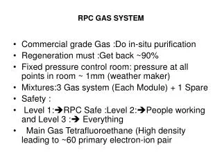
ISR - Test in progress • Open issues • Purification cycle • Effectiveness of the purification • Fresh mixture percentage needed • Stability of the system • The ISR lab has been converted to a site for the closed loop study • Few gaps equivalent to 5 RPCs under test with a closed loop prototype system. • 10 new Single Gap will be connected this week • All the detectors are inside a hut with temperature and humidity kept at controlled values • The mixture composition and quality are continuously monitored by means of a gas chromatograph • The new gas-chromatograph and mass-spectrometer (CERN Gas Group) will be connected to the pick-up lines this week.
Recent results New cycle started on July 25th Gas flow: 1 volume/2.5 h Gas quality checked every day with a GC Mixture recycle % injection vs time System stable for about two month, but now some sign of a small increase in the currents for the gaps operated in closed loop mode
(I(t)-I(0))/I(0) (I(t)-I(0))/I(0) open closed Recent results • The “up” gaps are mainly affected by the small increase in the currents. • Final check (10-15 days in open mode). Then switch again in closed mode with the “old” used purifiers to be sure that the increase is due the their saturation. • Then regenerate the purifiers and we will start a new cycle (most probably in January). Abnormal “air” level in the mixture (due to R134a cylinder impurity) RPCs switched off
R134a cylinder impurities • More than 13 R134a cylinders analyzed since July 15th with the Gas Chromatograph: • 6 cylinders < 500 ppm vol “air” • 3 cylinders ~ 4000 ppm vol “air” • 4 cylinders >> 30000 ppm vol “air” (plus an unknown component) • Some example (Gas chromatogram only): “good” cylinder Very “bad” cylinder
R134a cylinder impurities Further analyses will be performed in the next weeks with the GC-MS in order to identify the unknown component (most probably an other kind of freon) “good” cylinder Very “bad” cylinder Purged volume: 0 m3 ~1 m3 Unknown component: ~3 mV ~40 mV
Final remarks The commissioning of the final gas system is going on As usual we had/have many problems, but we are confident to start with the final mixture in 1-2 weeks In the mean time the CMS-RPC gas chromatograph will arrive and will be installed in SG5. Therefore, at the beginning of January, we will start the final commissioning of the purifiers In the closed loop test at ISR, after about two month of stability the detector currents has shown a small increase. The study is in progress in order to understand if the increase is due to the saturation of the purifiers. The new GC-MS (CERN Gas Group) will be installed at the ISR this week. It will help a lot in the understanding of the purifiers effectiveness. In one month also the new pH + Fluorine electrode station will be installed first at ISR and then in SG5.
Trigger Top Up Trigger Top Down Clean Mix Up CAEN V965 16Channel Dual Range Multievent QDC Clean Mix Down Front end electronics 80ns delay each channel IN Before Mix Up START Before Mix Middle TRIGGER 3/4 Before Mix Down Low Threshold Discriminators CAEN Power Supply SY1527 System 20ns Delay Slow Control After Mix Up Veto DAQ After Mix Middle After Mix Down Trigger Bottom Up Trigger Bottom Up Gas gain monitor Working at ISR
Gas gain monitor counts Pedestal Avalanche Streamer
The “leak” issue: summary System cannot handle the red cases (chamber does not keep any pressure). For the black cases it is possible to compensate the leak with higher flow.
The “leak” issue: possible causes Wrong operation of gas system: W+2, W+1 chambers have high input pressure due to old impedances valves. To deal with this, the gas rack safety bubbler was changed with a safety valve set to 70 mbar (instead of 10 mbar). Possible source of incident: output of the chamber not properly connected to the rack. However this would not explain cases in W0 Gas pipe damage inside the chamber In one case (chamber already substituted in W-1 due to a large leak), found a damage pipe inside the chamber. The chambers in W-1 have broken connectors (visible from outside). Gas pipe aging Very unlikely. Polyethylene pipe used. Aging cases never reported.
The “leak” issue: comments and actions Leak tests have been performed in all chambers during construction phase, after coupling to DT, before and after installation. A difference between input and output flow in some cells already observed during MTCC. However the precision of the calibration does not allow to draw conclusions. Also good performance of the chambers during MTCC and commissioning. This could lead to the conclusion that the leak is at the output. W+1, W+2 problematic chambers to be opened as soon as possible and replaced with new ones. All chambers ready to be replaced. W0 one chamber has a serious leak but we try to operate in open mode since no access possible to replace the chamber now.