Download
1 / 22
240 likes | 482 Vues
CHEMICAL REACTION ENGINEERING LABORATORY. Culturing Microalgae in Photobioreactors: Advanced Modeling and Experimentation. Muthanna H. Al-Dahhan and Hu-Ping Luo Bioreactor and Bioprocess Engineering Laboratory (BBEL) Chemical Reaction Engineering Laboratory (CREL)

E N D
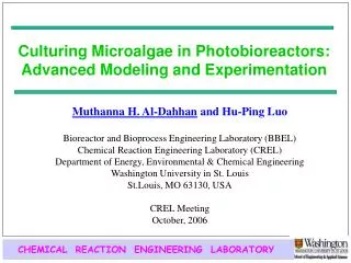
CHEMICAL REACTION ENGINEERING LABORATORY Culturing Microalgae in Photobioreactors: Advanced Modeling and Experimentation Muthanna H. Al-Dahhan and Hu-Ping Luo Bioreactor and Bioprocess Engineering Laboratory (BBEL) Chemical Reaction Engineering Laboratory (CREL) Department of Energy, Environmental & Chemical Engineering Washington University in St. Louis St.Louis, MO 63130, USA CREL Meeting October, 2006
CHEMICAL REACTION ENGINEERING LABORATORY Airlift Photobioreactors (PBR) for Microalgal/Cyanobacteria Cultures Microalgal/Cyanobacteria are cultured in closed photobioreactors for: • High value products • Health supplemental (i.e., Polyunsaturated Fatty Acids, Vitamins, Omega-3 Fatty Acids, …) • Biologically active substances (antiviral, antifungal) • Pigments (food color, fluorescent detection reagents, immunoassays) • Single Cell Protein (human, livestock) • Renewable energy • Methane, biodiesel, ethanol or hydrogen • Wastewater and animal wastes treatment • CO2 Fixation • Etc. Advantages of airlift reactors: • Desired mixing rate • Fair volume based production • High photosynthetic efficiency • etc.
Photobioreactors (PBR) – Problem Description Dark Center Io Irradiance field I(x,y,z) Bubbles CHEMICAL REACTION ENGINEERING LABORATORY light intensity gradient in a photobioreactor (PBR) The major problem is light: its availability and its use efficiency Cells’ Trajectory Photolimitation + Externalirradiance Photoinhibition Cells’ growth responds to the light history. Mixing, which induces the beneficial flashlight effects, can significantly enhance productivity
CHEMICAL REACTION ENGINEERING LABORATORY Hydrodynamics Affect: Cells’ Movements Light accessibility to the cells Liquid and Gas flow field Cells’ movements, light history Shear Stress High shear stress damages the cells Mass Transfer Access to the nutrient and remove O2 Concentration Distribution Light intensity distribution inside the reactor In-depth knowledge of hydrodynamics/flow pattern in the bioreactors is the key for design and scale-up. Advanced diagnostic techniques to characterize the local phenomena of the hydrodynamics are required However, the current modeling approach relies on static growth rate using the light availability on volume-averaged base (Ivav) Example: Molina Grima et al., 1997
CHEMICAL REACTION ENGINEERING LABORATORY Objectives • To advance the understanding of the hydrodynamics role in culturing microalgae and in photobioreactor performance • To develop a fundamental modeling approach for the growth of microaglae in photobioreactors for proper performance evaluation, design, and scale-up These can be achieved by: • Using advanced measurement techniques (CARPT and CT) to investigate in details the hydrodynamics in an draft tube column reactor • Analyzing and characterizing the interactions between hydrodynamics and photosynthesis • Developing and evaluating a new modeling approach that integrates the first principles of photosynthesis, hydrodynamics, and irradiance distributions in the reactor • Assess CFD modeling to obtain the needed hydrodynamics information for PBR analysis – a more accessible method for in-depth flow dynamic information
A New Approach for PBR Analysis and Modeling Experimental Techniques: CARPT and CT- CFD Simulation? Verification • Local multiphase flow dynamics: • Microorganism cells’ movements (x(t), y(t), z(t)) • Liquid flow dynamics (Velocity profile, Turbulent intensity, Shear Stresses, Macro-mixing, etc.) • Local phase distributions Modeling Irradiance Distribution, I (x, y, z) • Calculation of the temporal irradiance patterns, I(t) • Characterization of the interactions between hydrodynamics and Photosynthesis Model Evaluation by Real Culturing Experiments Fundamentally based modeling approach for PBR performance evaluation, design, scale-up, and process intensification Dynamic Photosynthetic Rate Model
Radioactive Scandium m Ci, emitting g (Sc 46, 250 rays) · embedded in 0.8~2.3 mm plolypropylene particle (neutrally buoyant with liquid) · m 100~150 m for solids in a slurry bubble column Power supply Connect to data acquisition NaI detectors held by Al supporter (not shown) Active surface of detector Distributor Gas inlet Example of Bubble column CHEMICAL REACTION ENGINEERING LABORATORY CARPT Technique Data Processing of Radiation Intensity Received by N Detectors from a Single Radioactive Sc-46 Particle Intensity “I” for N detectors (Photon counts) Calibration curves “I vs. D (distance)” Distance “D” from Particle to N detectors Weighted least square regression Particle Position Px,y,z (t) Filtering noise due to statistical fluctuation of g rays using Wavelet Analysis Filtered Particle position Px,y,z(t), cells’ movement Instantaneous Lagrangian Velocities Time Averaged velocities & Turbulence Parameters Computer Automated Radioactive Particle Tracking (CARPT) – Simulating the cells/liquid elements’ movement by a radioactive particle Detector Light Source Reactor with algae inside
CHEMICAL REACTION ENGINEERING LABORATORY Detector Collimator Lead Shielded Cs-137 Source Lead Plugs with Aperture Source Collimator 19.0 cm 3.5 0 NaI(Tl) Detector 29.0 cm 59.7 cm 8.4 cm 30.5 cm • Measurement of time-averaged cross-sectional phase holdup (volume fraction) distribution • Estimation-Maximization (EM) algorithm used for image reconstruction CT Technique Computed Tomography (CT) – Seeing through the reactor for phase distributions Detector Collimator Radiation Source Draft tube column
Structures to fix the sensor in the reactor center Irradiance Sensor 13 cm 9 cm Fluorescent m m Lamp c c 0 5 5 0 1 1 Riser e c n a r Air a e l C m o t t m Draft Tube o c B 3 Supports C C O o m 2 p r e s s e d Cotton Plug A i r CHEMICAL REACTION ENGINEERING LABORATORY • Experimental Procedure • Initially OD<0.01 (12 hrs) and Ug = 0.3cm/s • Turn on Four Lamps (275 mE/m2 s) • Turn on All Lamps (1850 mE/m2 s) @ OD=1.0 • Ug=1cm/s Reactor Conditions for CARPT &CT Experiments with/without Culturing Microalgae Draft Tube Column • Biomass Concentration Analysis • Dry biomass weight, g/L • Optical Density (OD) (Spectrotometer) • Cell No., Initial No.=106cell/ml • Chlorophyll a concentration, mg/ml • CARPT & CT Operating conditions with microalgaeand air-water systems • Optical Density (OD) = 0.2 ~ 0.6 • Ambient condition • Microalgae culturing / Air-water • Top clearance: 3cm / 0, 3, 6 cm • Bottom clearance: 5cm / 2, 5 cm • Ug=0.3 and 1cm/s / 0.076, 0.3, 0.82, 1 and 5 cm/s Profile of apparent viscosity versus shear stress at different biomass concentration
Particle Trajectories and Ergodicity Axial Average Number of Occurrence Per ml Typical Tracer Particle Trajectories
CHEMICAL REACTION ENGINEERING LABORATORY Photobioreactor Analysis IV –Particle (Cell) Tracking
Multiphase Flow Field Ug = 1 cm/s Bottom Clearance: 5cm Top Clearance: 3cm Without Mocroalgae Visualization of the Turbulent Kinetic Energies (TKE) Local gas holdup Axial liquid velocity
Draft tube column Split column Draft Tube Height, z, cm Height, z, cm (3) (2) Radial movements due to turbulence: Time scale: 0.1 s or less Spiral movements: Time scale: 1 s (1) y, cm CHEMICAL REACTION ENGINEERING LABORATORY CARPT Results — Cell’s trajectories Three types of mixing mechanisms have been identified in airlift photobioreactors via CARPT technique. These types of mixing induce beneficial light fluctuations delivered to the cells. Bulk liquid circulations: Time scale: 10 s Radius, r, cm Time and length scales show overlapping and interaction between flow dynamics and photosynthesis.
CHEMICAL REACTION ENGINEERING LABORATORY Photobioreactor Analysis I – Light History Lambert-Beer Law: (Evers, 1991) I(t), mE m-2 s-1 t, s Calculated temporal irradiance pattern (Calculation conditions: I0=2000E m-2s-1, x = 80106cells/ml) How to Characterize this process for reactor design, scale-up, and performance prediction ?
CHEMICAL REACTION ENGINEERING LABORATORY Photobioreactor Analysis I – Characterizing Light History Characteristic Parameters Light Fluctuation Parameters: Over-/Under charged cycles in chaotic temporal irradiance pattern • Time-averaged light intensity (Quantity of light transferred to the cells) Optimum irradiance Itav=90 E m-2 s-1, Ivav=164 irrespective of gas velocity and configuration) For Ug=1cm/s, high irradiance (2000 Em-2 s-1) and cell concentration (80*106 cells/ml) Over- charged Under- charged • Fluctuation Frequency: • f = 1 / (tover+tunder) Time series of irradiance experienced by the cells • Dimensionless relaxation time (fraction of over-charged time in a cycle): • j = tover/(tover+tunder)
CHEMICAL REACTION ENGINEERING LABORATORY Dynamic growth model representation: Photosythetic factory (PSF) approach Resting state Activated state Inhibited state (b) Structure of the three states model proposed by Eilers and Peeters (1988) (a) Schematic representation of the interaction of photosynthetic kinetics and the fluid dynamics in the photobioreactor (from Wu and Merchuk, 2001).
CHEMICAL REACTION ENGINEERING LABORATORY Photobioreactor Analysis II – Integrating Kinetics and Hydrodynamics Luo & Al-Dahhan, Biotech. & Bioeng., 85(4), 382, 2004 Differential equations: (1) (2) (3) (4) x1+x2+x3=1 Growth rate: (5) Kinetic model for photosynthesis (Eilers and Peeters, 1988) (6) Shear Stress (Wu and Merchuk, 2001) Light History: I = f (t, cell positions) Initial conditions: x1 = 1, x2 = x3 = 0, t = 0
CHEMICAL REACTION ENGINEERING LABORATORY Simulation results by the dynamic model for the draft tube column (on the right) at Ug of 1 cm/s. The experimental data (Merchuk, et al., 2000) are based on the draft tube column on the left at the superficial gas velocity of 0.29 cm/s.
Model Predictions Prediction of the dynamic model using CARPT data obtained in microalgae culturing system and in air-water system. The time-averaged light intensities were calculated by Case I (i.e., External Irradiance=250E m-2 s-1; Cell concentration=8106 cells/ml). The data are from Wu and Merchuk (2001). In the dynamic simulation, the values of k and Me are half of the values proposed by Wu and Merchuk (2001).
CHEMICAL REACTION ENGINEERING LABORATORY Can CFD provide the needed information for microalgae dynamic growth modeling ? Apparent viscosity Air-water system CFD/CARPT results after validating the closure Shear stress CFD is not yet ready to be used under dynamic growth of microalgae
Summary • Using CARPT and CT techniques, the local flow dynamics in a draft tube column reactor were studied, providing in-depth knowledge for PBR analysis, design, and scale-up. • Three types of mixing mechanisms with different time scales were found in the airlift column reactors, which can introduce light fluctuations to the cells. • The temporal irradiance patterns were calculated and further quantitatively characterized by three parameters: the time averaged irradiance, the frequency of the over-/under- charged cycles, and the dimensionless relaxation time. • A new dynamic modeling approach was developed for culturing microalgae in PBR. This general approach integrates first principles of photosynthesis, hydrodynamics, and irradiance distribution within the reactor. • The developed dynamic growth rate model predicted the trend and the reactor performances measured in this study and the performance measured by Merchuk et al. (2000). • Work is needed to advance the CFD models and closures to properly simulate the hydrodynamics of photobioreactors under dynamic growth of microalgae. • Upon such advancement, CFD would have the potential to be integrated along the newly developed approach to predict the microalgae culturing in photobioreactors.
CHEMICAL REACTION ENGINEERING LABORATORY Acknowledgement • CREL sponsors • DOE • Dr. Xiaoxi Wu (Rutgers University) • Dr. Miguel Olaizola (Green Fuel Inc.)