Chapter 6 System Engineering
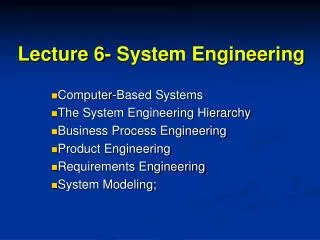
Chapter 6 System Engineering. Business or Product Domain. 6.2 The System Engineering Hierarchy. World view. Domain of interest. Domain view. Software, hardware, people, database, documentation, procedures. System element. Element view. Detailed view. 1/11.

Chapter 6 System Engineering
E N D
Presentation Transcript
Business or Product Domain 6.2 The System Engineering Hierarchy World view Domain of interest Domain view Software, hardware, people, database, documentation, procedures System element Element view Detailed view 1/11
6.3 Business Process Engineering • Goal: define architecture that will enable a business to use information effectively • Architectures to be analyzed and designed within the context of business objectives and goals: • data architecture provides a framework for the information needs of a business or business function • application architecture encompasses those elements of a system that transform objects within the data architecture for some business purpose • technology infrastructure provides the foundation for the data and application architectures 2/11
The enterprise Information strategy planning (ISP) Business area analysis (BAA) Business system design Construction and integration 6.3 Business Process Engineering 3/11
6.4 ProductEngineering • Goal: translate the customer’s desire for a set of defined capabilities into a working product. 4/11
Every computer-based system can be modeled as an information transform using an input-processing-output template. 6.5 System Modeling 5/11
Example: Conveyor Line Sorting System • Determine bin location • Produce control signal for shunt • Maintain record of box destinations • Read bar code input • Read pulse tachometer • Decode part code data • Do database look-up 6/11
UML – Unified Modeling Language CLSS processor Deployment diagram for CLSS hardware Sorting subsystem Operator display Sensor data acquisition subsystem Shunt controller Conveyor pulse tach Bar code reader Shunt actuator 6.5 System Modeling 8/11
Activitydiagramfor procedural aspects of CLSS software Valid bar code Invalid bar code Conveyor in motion Conveyor stopped 9/11
UML Class diagram for Box class Class name Box barcode forwardSpeed conveyorLocation height width depth weight contents Attributes Operations (parentheses at end of name indicate the list of attributes that the operation requires) readBarcode() updateSpeed() readSpeed() updateLocation() readLocation() getDimensions() getWeight() checkContents() 10/11
Use-case diagram for CLSS operator Request bar code Request shunt control status Request box processing report Update product database CLSS operator Run system diagnostics 11/11