Blue Print Reading Level 1 Overview
270 likes | 451 Vues
Prints: the Language of Industry You have heard the saying, “A picture is worth a thousand words”. This is certainly true when referring to an airplane part.

Blue Print Reading Level 1 Overview
E N D
Presentation Transcript
Prints: the Language of Industry You have heard the saying, “A picture is worth a thousand words”. This is certainly true when referring to an airplane part. It would be next to impossible for an engineer or designer to describe in words the shape, size, and relationship of the various parts of an airplane in enough detail for skilled workers to produce the part. Drawings are the universal language used by engineers, designers, and skilled workers to share quickly and accurately the necessary information to create parts, put together and service airplanes and other complex assemblies. The original drawing that is created in an engineering department is kept in a vault, and paper and Mylar copies are made to be used on the shop floor. Drawings used to be done by hand on Mylar, a thin plastic sheet, but now are created on Catia, AutoCAD or other 3-D graphic system. A print is a copy of the drawing that shows what the object will look like when it is completed. Regardless of the color, the terms “drawing”, “print” and “blueprint” all mean the same thing when referring to copies of the engineering drawing. Prints provide you with details like size and shape description, tolerances (allowable error) to be held, materials used, finish, and other treatments. Blue Print Reading Level 1Overview
Print reading is getting information from a print. This task involves visualization and interpretation of the print. Visualization is the ability to “see” or imagine the size and shape of the object from prints that show views.
The ability to interpret, or understand, the lines, symbols, dimensions, notes and other information on the part is the other important part of print reading. Some common lines, symbols, dimensions and notes
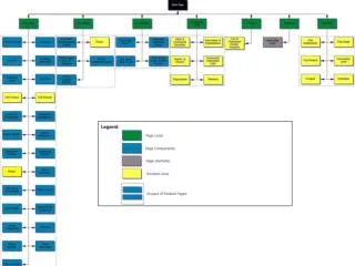
A print is the drawing of an object, but there is not enough information on a print to accurately create the part. You also need the parts list, and reference information. Picture sheet: The picture sheet shows: • What the part looks like • Size and shape of the parts • How the parts ands assemblies fit together • Where the parts and assemblies are installed The picture sheet shows the part with enough views to completely describe the part. The part is shown in a two dimensional (flat) view. Picture sheets contain dimensions, symbols, and tolerances. Parts list: The parts list contains: • List of material- what you need to build the part • General notes/Flag notes – more information on how to build the part • Part marking and finishing information flag note 3 • List of specifications- other documents that tell you how to install fasteners, paint, part mark, etc... Reference Information: Reference information includes: Work order/traveler Customer specifications
The Definition of Lines On aerospace drawings, 9 types of lines are commonly used. Each has a particular meaning to the engineer, and a skilled worker must recognize and understand the meaning of the lines to correctly interpret the print. 1. Visibleline: the visible line is a thick continuous line that represents all edges and surfaces of an object that are visible in that view __________________________________________________________ • Hidden line: hidden lines have short dashes, and are used to show edges, surfaces and corners not visible in a particular view.
3. Centerline: center lines are a thin line with one short dash between two long dashes. They are used to show the centers of holes, arcs, and symmetrical parts (symmetrical means both sides are identical). Sometimes you will see the symbol CL, or to designate a centerline, and SYM to tell you the part is symmetrical around the centerline. 4. Dimensionline: dimension lines are thin lines that have arrows on both ends, and a dimension, or measurement, in between. 5. Extensionline: an extension line is a thin line, used to place a dimension away from the part, to make it easier to read
6. Leader line: leaders are thin lines with one arrow that point to an area, and give specific information about that area. 7. Cutting Plane lines/Section View lines: the cutting plane is a thick line, often with a 90° bend, that ends with an arrow. They are used in pairs, when we need to “cut” a part open to see more detail. The arrows indicate the direction your eyes are looking. On Boeing prints, each section view is named; for example, 1A2C4, which means this is the first section cut in zone A2, and the section view is located in zone C4. Name 1A2 C4 address 1A2C4
Section View Example The -5 is located in zone B3. Section cut 1C3C2 is the first cut in zone C3, and the view is located in zone C2. The name of the view, “1C3”, stays with the view. Section cut 1D3A2 is from zone D3, and the view is located in zone A2.
8. Referenceline: a thin line with two dashes. Reference lines are used to show alternate position, adjacent parts, or repeated detail.
9. Breaklines: break lines are used to show that there is more to the part than is being shown. Some break lines are wavy lines, some are angular lines.
Orthographic Projection The purpose of a drawing is to show the size and shape of an object, and to provide certain information on how it is to be made. The best way to show every feature of a part in its true size and shape is to use a multi-view orthographic projection drawing. Aerospace drawings often use three views of a part, and these views are drawn so that every feature can be seen and dimensioned. On some newer prints, there is an isometric (3D) view of the part in the upper right corner of the drawing. These not-to-scale views are to help you “see” the part. Isometric drawings really help you understand what the part or assembly is to look like, but they can’t be accurately dimensioned. After completing this chapter, you will be able to: Identify an orthographic projection drawing Identify objects shown in an orthographic projection drawing See how the three standard views can describe a part.
The different views on an orthographic projection drawing are arranged in a systematic way so the print reader may mentally connect them together and form an image. Top Isometric view 3D Front Side Orthographic view 2D
The views of an orthographic drawing are projected at right angles to each other, and have a definite relationship. One way to visualize the relationship between views is to imagine that the part being placed in a glass box, and only one side of the part can be seen at a time. You can “see” where the surfaces in one view will show as lines on another views, and how holes in one view can be shown with hidden lines in other views. When the part is placed in the glass box, there are six possible views- top, front, right side, left side, bottom and rear. Usually a part can be described in three views, so the views most often used on orthographic drawings are top, front, and right side.
Some parts, usually round shaped parts, can be shown in two views, since two of the views are identical.
When you look at a multi-view drawing, here are some steps that might help in visualizing the actual part: • Scan briefly all the views shown • Study the front view for shape description • Move from the front view to the other views and look for lines that describe the intersections of surfaces, the limits of a surface, or the edge view of a surface • Study one feature at a time, looking at each view, and begin to picture in your mind the shape of the real object Being able to link the 2D views into a 3D image in your mind takes practice. Don’t be discouraged if you need to sketch pictures, or break the part into simple geometric shapes before you can visualize how the views of the drawing will result in an actual part.
Full Size Half size 2.5 Scale: 1/1 2.5 Scale: 1/2 Twice Size 2.5 Scale: 2/1 Picture sheet scale Some parts are so large they won’t fit on a drawing sheet, even a big drawing sheet. And some parts are so small; you would need a magnifying glass to see them. To help you figure out what the part needs to look like, the “scale” of the drawing is important. Scale is the relationship between the actual size of the part to the part shown on the print. Large parts may be drawn half size (scale ½), so they will fit on the drawing sheet. Small parts can drawn at twice size (scale 2/1), so you can see every detail. Most aerospace prints are drawn full size- for every inch on the part; there is an inch on the drawing. Some drawings may have views that are drawn at different scales. Any view that is not drawn at full size (scale 1/1) will have a note underneath, calling out the scale. The scale callout in the title block will also give you this information. The called out dimension is not affected by the scale. PCMs are always drawn full size.
2782.2 231’ 10.2” Airplanes, houses, and buildings are drawn smaller than they are, so you can see the whole structure on one piece of paper. .100 4 inches = 1 inch Computer chips are drawn larger than they are, to show all the details. The dimensions are accurate, just the picture is larger.
Drawing Notes and Symbols Sometimes you need more information to build a part then just dimensions. Notes are often on drawings to provide you with more details for a part or a process. Most of the notes that used to be located on the picture sheets have been moved to the Parts List, but some notes are still essential on the picture sheet. There are two types of notes; general notes which can apply to the entire drawing, or just to a specified area, and flag notes which are shown by a symbol and apply only where they are called out. Examples of general drawing notes: 125 RA micro inches or better surface finish Typical fillet except as noted Flag notes, are used on the face of the drawing to avoid repeating information. They generally use numbers to tell them apart. To find out what a particular flag note means, you look in up in the Flagnotes- General Notes section of the Parts List. Examples of flag notes:
Examples of flag notes: On the picture sheet Notes are in Parts List Symbol Definitions of Flagnotes-General found on DWG are located in Parts list. 1 FL 1 This area finished with F-17.33 6 FL 6 Shim gap in excess of .03
Common symbols T is a Tool Hole, a 0.247-0.250 hole used by Manufacturing H G C is a PCM Grid Check point Ø means diameter, the distance across a hole R means radius, the distance from the center to the edge of the hole F/P means flat pattern Is a fastener symbol, where a rivet or bolt will be installed. Is a hole location for a fastener. This diameter will always be in 32nds. TYP means Typical, that the callout will be the same in several places
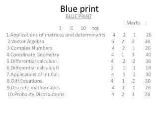
Dimensions and Tolerances Most major industries do not manufacture all of the parts and sub- assemblies required in their products. For instance, there are 3 million parts in a Boeing 777, provided by more than 900 suppliers. Frequently these parts are manufactured by specialty industries, to specifications provided by the major industry. The key to successful operation of the various parts and sub-assemblies in the major product is the ability of two or more nearly identical duplicate parts to be used in an assembly and function satisfactorily. Here are some standard terms used on and about prints. Tolerance is the amount of variation permitted from the design size of a part. Tolerances can be shown by the variations between limits, 1.525- 1.530 as the dimension size followed by the tolerance, 1.455 ± .002 and when one tolerance value is given (the other is assumed to be zero) 1.825 + .003 On a print, if a dimension does not have a tolerance next to it, use the tolerance called out next to the title block. If a dimension does have a called out tolerance, you must use that tolerance.
Decimal Place Value 1. 2 3 4 5 The numbers to the left of the decimal are whole numbers. The numbers on the right side of the decimal are fractions of a whole number. 1.25 could be said as “one and a quarter inch”, or “one point two five”, or “one and twenty five hundredths”. 5.389 could be said as “five and three hundred eight-nine thousandths”. Types of Dimensions Linear dimensions on aerospace drawings are given in inches and decimal fractions. For example: 5.390
Angular dimensions are used on prints to indicate the size of angles in degrees (°), and the fractional parts of a degree; minutes ( ´ ) and seconds ( ´´ ). A complete circle contains 360 ° (degrees), one degree contains 60 ´ (minutes), and one minute contains 60´´ (seconds). Reference dimensions are occasionally given on drawings for reference and checking purposes. These dimensions are followed by the word REF. They will be without tolerance, and are not to be used for layout, machining or inspection operations.
Tabular dimensions are used when a company manufactures a series of sizes of a part. Dimensions on the drawing are replaced by reference letters and a table on the drawing lists the corresponding dimensions.