Download
1 / 83
840 likes | 880 Vues
Learn about epipolar geometry, essential matrix, and fundamental matrix in computer vision, with examples and applications in stereo systems and depth estimation. Explore correspondence search methods and stereo matching algorithms.

E N D
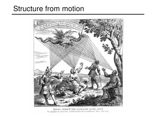
Structure from Motion and Optical Flow Various slides from previous courses by: D.A. Forsyth (Berkeley / UIUC), I. Kokkinos (Ecole Centrale / UCL). S. Lazebnik (UNC / UIUC), S. Seitz (MSR / Facebook), J. Hays (Brown / Georgia Tech), A. Berg (Stony Brook / UNC), D. Samaras (Stony Brook) . J. M. Frahm (UNC), V. Ordonez (UVA), Steve Seitz (UW).
Last Class • More on Epipolar Geometry • Essential Matrix • Fundamental Matrix
Today’s Class • More on Epipolar Geometry • Essential Matrix • Fundamental Matrix • Optical Flow
Estimating depth with stereo Stereo: shape from “motion” between two views We’ll need to consider: Info on camera pose (“calibration”) Image point correspondences scene point image plane optical center
Key idea: Epipolar constraint X X X x x’ x’ x’ Potential matches for x have to lie on the corresponding line l’. Potential matches for x’ have to lie on the corresponding line l.
Epipolar geometry: notation X x x’ • Baseline – line connecting the two camera centers • Epipoles • = intersections of baseline with image planes • = projections of the other camera center • Epipolar Plane – plane containing baseline (1D family)
Epipolar geometry: notation X x x’ • Baseline – line connecting the two camera centers • Epipoles • = intersections of baseline with image planes • = projections of the other camera center • Epipolar Plane – plane containing baseline (1D family) • Epipolar Lines - intersections of epipolar plane with image planes (always come in corresponding pairs)
Epipolar Geometry: Another example Credit: William Hoff, Colorado School of Mines
Geometry for a simple stereo system First, assuming parallel optical axes, known camera parameters (i.e., calibrated cameras):
Simplest Case: Parallel images • Image planes of cameras are parallel to each other and to the baseline • Camera centers are at same height • Focal lengths are the same • Then epipolar lines fall along the horizontal scan lines of the images
Geometry for a simple stereo system Similar triangles (pl, P, pr) and (Ol, P, Or): disparity Assume parallel optical axes, known camera parameters (i.e., calibrated cameras). What is expression for Z?
Depth from disparity image I´(x´,y´) image I(x,y) Disparity map D(x,y) (x´,y´)=(x+D(x,y), y) So if we could find the corresponding points in two images, we could estimate relative depth…
Correspondence search Left Right • Slide a window along the right scanline and compare contents of that window with the reference window in the left image • Matching cost: SSD or normalized correlation scanline Matching cost disparity
Correspondence search Left Right scanline SSD
Correspondence search Left Right scanline Norm. corr
Basic stereo matching algorithm • If necessary, rectify the two stereo images to transform epipolar lines into scanlines • For each pixel x in the first image • Find corresponding epipolarscanline in the right image • Examine all pixels on the scanline and pick the best match x’ • Compute disparity x–x’ and set depth(x) = B*f/(x–x’)
Failures of correspondence search Occlusions, repetition Textureless surfaces Non-Lambertian surfaces, specularities
camera • projector Active stereo with structured light • Project “structured” light patterns onto the object • Simplifies the correspondence problem • Allows us to use only one camera • L. Zhang, B. Curless, and S. M. Seitz. Rapid Shape Acquisition Using Color Structured Light and Multi-pass Dynamic Programming.3DPVT 2002
Kinect and Iphone X Solution • Add Texture!
Kinect: Structured infrared light • http://bbzippo.wordpress.com/2010/11/28/kinect-in-infrared/
Basic stereo matching algorithm • If necessary, rectify the two stereo images to transform epipolar lines into scanlines • For each pixel x in the first image • Find corresponding epipolarscanline in the right image • Examine all pixels on the scanline and pick the best match x’ • Compute disparity x–x’ and set depth(x) = B*f/(x–x’)
Effect of window size • Smaller window • More detail • More noise • Larger window • Smoother disparity maps • Less detail W = 3 W = 20
Results with window search Data Window-based matching Ground truth
Better methods exist... Ground truth Graph cuts • Y. Boykov, O. Veksler, and R. Zabih, Fast Approximate Energy Minimization via Graph Cuts, PAMI 2001 • For the latest and greatest: http://www.middlebury.edu/stereo/
When cameras are not aligned:Stereo image rectification • Reproject image planes onto a common • plane parallel to the line between optical centers • Pixel motion is horizontal after this transformation • Two homographies (3x3 transform), one for each input image reprojection • C. Loop and Z. Zhang. Computing Rectifying Homographies for Stereo Vision. IEEE Conf. Computer Vision and Pattern Recognition, 1999.
Back to the General Problem Credit: William Hoff, Colorado School of Mines
Back to the General Problem Credit: William Hoff, Colorado School of Mines
Back to the General Problem Credit: William Hoff, Colorado School of Mines
Back to the General Problem Credit: William Hoff, Colorado School of Mines
Back to the General Problem Credit: William Hoff, Colorado School of Mines
Back to the General Problem Credit: William Hoff, Colorado School of Mines
Back to the General Problem Credit: William Hoff, Colorado School of Mines
Brief Digression: Cross Product as Matrix Multiplication • Dot Product as matrix multiplication: Easy • Cross Product as matrix multiplication:
Back to the General Problem Credit: William Hoff, Colorado School of Mines
The Essential Matrix Essential Matrix (Longuet-Higgins, 1981) Credit: William Hoff, Colorado School of Mines
Epipolar constraint: Calibrated case X • Intrinsic and extrinsic parameters of the cameras are known, world coordinate system is set to that of the first camera • Then the projection matrices are given by K[I | 0] andK’[R | t] • We can multiply the projection matrices (and the image points) by the inverse of the calibration matrices to get normalized image coordinates: x x’
Epipolar constraint: Calibrated case X = (x,1)T x x’ = Rx+t t R The vectors Rx, t, and x’ are coplanar
Epipolar constraint: Calibrated case X x x’ = Rx+t Recall: The vectors Rx, t, and x’ are coplanar
Epipolar constraint: Calibrated case X x x’ = Rx+t Essential Matrix (Longuet-Higgins, 1981) The vectors Rx, t, and x’ are coplanar
Epipolar constraint: Calibrated case X • E x is the epipolar line associated with x(l' = E x) • Recall: a line is given by ax + by + c = 0 or x x’
Epipolar constraint: Calibrated case X • E x is the epipolar line associated with x(l' = E x) • ETx'is the epipolar line associated with x'(l = ETx') • E e= 0 and ETe' = 0 • Eis singular (rank two) • E has five degrees of freedom x x’
Epipolar constraint: Uncalibrated case X • The calibration matrices K and K’ of the two cameras are unknown • We can write the epipolar constraint in terms of unknown normalized coordinates: x x’
Epipolar constraint: Uncalibrated case X x x’ Fundamental Matrix (Faugeras and Luong, 1992)
Epipolar constraint: Uncalibrated case X x x’ • F x is the epipolar line associated with x(l' = F x) • FTx' is the epipolar line associated with x' (l = FTx') • F e= 0 and FTe' = 0 • Fis singular (rank two) • F has seven degrees of freedom
Estimating the Fundamental Matrix • 8-point algorithm • Least squares solution using SVD on equations from 8 pairs of correspondences • Enforce det(F)=0 constraint using SVD on F • 7-point algorithm • Use least squares to solve for null space (two vectors) using SVD and 7 pairs of correspondences • Solve for linear combination of null space vectors that satisfies det(F)=0 • Minimize reprojection error • Non-linear least squares Note: estimation of F (or E) is degenerate for a planar scene.
8-point algorithm • Solve a system of homogeneous linear equations • Write down the system of equations =0