Download

1 / 23
280 likes | 866 Vues
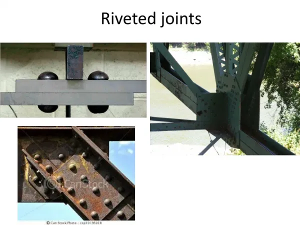
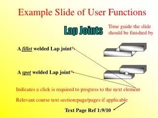
Photoelastic Study of Non-Riveted Lap Joints. Deonna Woolard and William Pluim Randolph-Macon College CSAAPT April 21, 2001. Types of Lap Joints. a) Glued scarf joint in timber b) Butt-weld in metal c) Welded Lap joint d) Riveted Lap joint.

E N D
Photoelastic Study of Non-Riveted Lap Joints Deonna Woolard and William Pluim Randolph-Macon College CSAAPT April 21, 2001
Types of Lap Joints a) Glued scarf joint in timber b) Butt-weld in metal c) Welded Lap joint d) Riveted Lap joint (Structures by J.E. Gordon, pages 136-138)
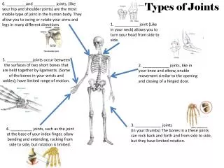
Modes of Failure a) Failure by shearing the rivets b) Failure by tearing the rivets out of the plate c) Failure by tearing the plate (Structures by J.E. Gordon, pages 142)
Non-Riveted Lap Joints • Modern adhesives offer an alternative to joints made with rivets • Adhesives permit similar or dissimilar materials to be jointed without harming the materials themselves • Using an adhesive on the full overlapped area distributes the load across the entire area of the bond reducing stress concentrations • The geometry of structures can get more complex with non-riveted lap joints
Photoelasticity and Lap Joints Although the lap joint is commonly used in design, properties and reactions of non-riveted lap joints under load are still widely unknown. Photoelasticity
Photoelastic Effect Polarizer Material Analyzer
Photoelasticity by Reflection Polarizer 1/4 Wave Plate Light Source Photoelastic Coating Test Part 1/4 Wave Plate Polarizer observer
Isoclinic vs. Isochromatic Linear Polarization Circular Polarization
Non-Riveted Lap Joints The lap joints were built from aluminum and acrylic strips, and bonded with two department store adhesives, Weldit and 5-Minute Fast Drying Epoxy, and the PC-1 adhesive from The Measurements Group. The acrylic is photoelastic by itself, but also clear so a reflective paint was applied to the back of the joints. The aluminum samples were reflective, but a photoelastic coating was required to allow photoelastic analysis.
The initial samples did not take more than 25 lbs of load from the frame. The acrylic laps broke due to chips in the cut edges. The reflective paint aggravated the chips into cracks. The Weldit cement did not hold even after roughing up the surfaces of the laps. Sanding the surfaces that were bonded made them hold up to greater loads. A local glass company cut laps and polished the edges so there were no chips to crack. Use of the Weldit cement was discontinued due to lack of results. Preparation, Problems, and Solutions Problem Solution
Lap Joint Failure Data 1) Al .05cm 5-Min 2) Al .1 cm 5-Min 3) Al .1 cm PC-1 4) Al .3 cm 5-Min 5) Al .3 cm PC-1 6) Al .3 cm Weldit 7) Ac .3 cm 5-Min 8) Ac .3 cm PC-1
Aluminum Fringe Fringe Movement on Aluminum Joint with PC-1 Adhesive
Fringe ‘Velocity’ Fringe velocity for Al sample. Load dependent fringe with load increasing with time.
Finite Element Analysis (FEA) • To better understand the mechanisms behind a lap joint under load. • FEA is used for situation where there is no closed mathematical solution to the problem. • A commercial software package, COSMOS/M, was used. • It allowed us to build the model in a three-dimensional wireframe, apply boundary conditions to the model, and analyze the behavior of the lap joint under controlled loads and conditions.
COSMOS/M Model Wireframe model of a Non-Riveted Lap Joint
Explanation of Sample Results FEA view of the top strip of a lap joint FEA view of an internal section of the bond
Proposed theory Proposed theory for deformation as load increases from top to bottom It was theorized that an out of plane deformation was causing the joint to bend, and the crease created by the bend caused the fringe to move as the load increased.
FEA Deformation Lower Limit Response Max. Def: 1.13E-6 Upper Limit Response Max Def: 1.13E-5
Conclusions • Photoelasticity not effective in monitoring lap joint health • Surface was inactive under photoelastic analysis • The bond took the majority of the load • The load did not transmit to the surface • Fringe movement on the sample due to out of plane deformation
Suggestions for Future Work • Determine elastic modulus of the adhesives • Further refine COSMOS/M model • Further study the out of plane deformation of the lap joint