Lap Joints
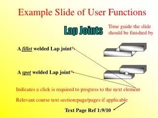
Example Slide of User Functions. Time guide the slide should be finished by. Lap Joints. A fillet welded Lap joint *. A spot welded Lap joint *. Indicates a click is required to progress to the next element. Relevant course text section : page/pages if applicable. Text Page Ref 1:9/10.

Lap Joints
E N D
Presentation Transcript
Example Slide of User Functions Time guide the slide should be finished by Lap Joints A fillet welded Lap joint* A spot welded Lap joint* Indicates a click is required to progress to the next element Relevant course text section:page/pages if applicable Text Page Ref 1:9/10
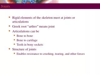
Terms & Definitions A union between materials caused by heat, and or pressure A Weld:* A Joint:* A configuration of members Text Page Ref 1:1
Types of Welds Butt welds:* Fillet welds:* Spot/Seam welds:* Plug/Slot welds:* Edge welds:*
Types of Joints Butt joints:* T joints: * Lap joints:* Corner joints:* Closed corner Open corner*
Weld Preparations Remember, the purposes of a weld preparation is to allow access for the welding process, penetration and fusion through the area of the joint and its faces* The basic rule is this: The more you take out, then the more you must put back in* This has major effects on economics and distortion control etc The root face, root gap and angle of bevel values, the choice of single, or double sided preparations, are dictated only by the type of welding process, the position and accessibility of the joint*
Weld Preparations Angle of bevel* Root face* Included angle* Root gap* Root radius* Root landing*
Types of Single Butt Preparation Single bevel Single V Single J Single U*
Types of Double Butt Preparation Double bevel Double V Double J Double U*
Welded Joints Butt Joints A butt welded butt joint* A fillet welded butt joint* A compound welded butt joint*
Welded Joints T Joints A fillet welded T joint* A butt welded T joint* A compound welded T joint*
Welded Joints Lap Joints A fillet welded Lap joint* A spot welded Lap joint* A compound welded Lap joint*
Welded Joints Closed Corner Joints A fillet welded Closed Corner joint* A butt welded Closed Corner joint* A compound welded Closed Corner joint*
Welded Joints Open Corner Joints An inside fillet welded Open Corner joint* An outside fillet welded Open Corner joint* A double fillet welded Open Corner joint*
A Butt Welded Butt Joint Weld Face* Actual Throat Thickness* Weld Width* 1.2.3.4. Weld Toes* Design Throat Thickness* 1 2 A 3 4 B Fusion Boundary* HAZ* Weld Root* Fusion Zone* A + B = Excess Weld Metal**
Sizing of Fillet Welds Vertical Leg Length* Weld face* Horizontal Leg Length* Excess weld metal** Design throat* Actual throat*
Nominal & Effective Throat Thickness “a” = Nominal throat thickness “s” = Effective throat thickness a s Deep throat fillet welds from FCAW & SAW etc*
Fillet Weld Profiles Concave Mitre Convex * Concave is preferred for joints subject to fatigue loading
Effect of a Poor Toe Blend Angle 6 mm 80° Very Poor Weld Toe Blend Angle 3 mm* 20° Improved Weld Toe Blend Angle
Effect of a Poor Toe Blend Angle It is also possible that the height of excess weld metal is within the acceptedlimit of an applied standard, but the toe blend is unacceptable, as shown below* 90° 3 mm Extremely poor toe blend, but excess weld metal is within limits*
Summary of Terms Weld: A Union of materials Joint: A Configuration of members Weld Preparation:Preparing a joint to allow access and fusion. Types of Weld: Butt. Fillet. Spot. Seam Plug. Slot. Edge. Types of Joint:Butt. T. Lap. Corner (Open & Closed) Types of Preparation: Bevel’s. V’s. J’s. U’s. Single & Double Sided. Preparation Terms:Bevel/included angle. Root face/gap. Land/Radius Weldment Terms: Weld face & root. Fusion zone & boundary. HAZ. Weld toes.Weld width Weld Sizing (Butts): DTT. ATT. Excess weld metal. Weld Sizing (Fillets): DTT. ATT. Excess weld metal. Leg length *
Duties of a Welding Inspector It is the duty of all welding inspectors: To ensure that welding operations are carried out in accordance with written, or agreed practices or specifications Before During After * All Welding Operations Describe your duties to your code of practise. “CSWIP Exam”*
Duties of a Welding Inspector Discuss the following Before Welding: • Safety: Legislation and safe working practices • Documentation: Spec. Drawings. Procedures. Welder approvals. Certificates. Mill sheets • Welding Process and ancillaries:Equipment. Cables. Regulators. Ovens. Quivers etc • Incoming Consumables: • Materials/welding consumables (Size. Condition. Specification. Storage) • Marking out preparation & set up: Method. Angles/Root face/gap values. Distortion control. Pre-heat prior to tack welding if applicable*
Duties of a Welding Inspector During Welding: • Pre-Heating. (Method and control) • In process distortion control (Balance or sequence welding) • Consumable control. (Correct baking and storage prior to use) • Welding process (Related parameters i.e. volts/amps. gas flow rate) • Welding run sequence and inter-pass cleaning • Minimum/maximum Inter-pass temperatures • Full compliance with all elements given on the WPS*
Duties of a Welding Inspector After Welding: • Visual Inspection • Non Destructive testing • Repairs* • Repair procedures (NDT/Excavation/Welding/Welder approval) • PWHT • Hydro-static testing • Submission of all inspection reports to QC departments*
Responsibilities of a Welding Inspector To Observe Activities & Imperfections* Activities & Imperfections* To Record Activities & Imperfections* To Compare
Attributes of an effective Welding Inspector Some attributes/skills of an effective Welding Inspector:* • Honest • Literate • Respected • Dedicated • Impartial • Observant • Decisive • Analytical* • Knowledgeable • Experienced • Record keeping skills • Communication skills • Safety conscious • Inquisitive • Responsible • Diplomatic skills*
A Welding Inspectors Toolbox A Welding Inspectors toolbox should contain* A welding gauge (Cambridge style, or high low gauges etc) A tape measure and scale A wire brush A magnifying glass A torch and mirror A specification, pen and report, or note paper Any other aids to visual inspection*
Specialised Aids for Inspection Inspection may utilise the following specialised equipment:* Boroscopes (For assessing root runs in small Ø pipes) Flow-meter (For measuring gas flow rates in MIG/MAG/TIG) Simple NDT equipment (Penetrants and MPI) Complex NDT equipment (Radiography or Ultrasonics) Note: Both simple and complex NDT methods requires the specialised skills of qualified operators/technicians*
Imperfections in Welded Joints Welding imperfections can be categorized into groups: 1) Cracks 2) Gas Pores & Porosity 3) Solid Inclusions 4) Lack of fusion 5) Profile & Lack of Filling 6) Mechanical or Surface damage 7) Misalignment*
Cracks A HAZ hydrogen crack, initiated at the weld toe Most cracks are initiated from stress concentrations *
Gas pores and Porosity Surface breaking porosity Shrinkage cavity* Coarse cluster porosity Fine cluster porosity Blow hole > 1.6 mm Ø An isolated internal porosity Hollow root bead
Solid Inclusions Surface breaking solid inclusion Internal solid inclusion causing a lack of inter-run fusion* Internal solid inclusion causing a lack of sidewall fusion Solid inclusions caused by undercut in the previous weld run Internal solid inclusion
Lack of Fusion Lack of sidewall fusion & incompletely filled grove* Overlap (Causing cold laps) Lack of inter-run fusion Lack of sidewall fusion Lack of root fusion
Profile Imperfections Spatter An Incompletely filled groove A Lack of rootfusion Bulbous, or irregular contour Arc Strikes Poor toe blend B Incomplete root penetration *
Profile Imperfections Shrinkage grooves Root concavity Crater pipe * Root oxidation in Stainless Steel Excess penetration, and burn through
Undercut in Butt Welds Root Run or “Hot pass” undercut Parent metal, surface undercut Weld metal, surface undercut*
Undercut in Fillet Welds Weld metal, surface undercut Parent metal, “top toe” undercut*
Mechanical and Surface Damage Any surface damage caused by: Grinding Hammering/chisel marks Slag chipping hammer marks Torn cleats (Hammered off attachments) Arc strikes All of the above may cause serious weakness to the weld area*
Misalignment Linear Excess weld metal height Lowest plate to highest point 3 mm Linear misalignment measured in mm Angular 15 Angular misalignment measured in degrees*
Mechanical Testing Why ?* To establish the level of mechanicalproperties* Which properties ?* 1) Hardness* 2) Toughness* 3) Tensile strength* 4) Ductility*
What are Mechanical Properties? Describes the actions of “force & motion” Mechanical:* Properties:* Something that makes one material useful for a job. These include the properties of: Hardness:* The ability of a material to resist indentation Toughness:* The ability of a material to absorb impact energy Tensile strength:* The ability to resist the action of a pulling force Ductility:* The ability to deform plastically under tension*
Introduction to Mechanical Testing We test welds to establish minimum levels of mechanical properties, and soundness of the welded joint* We divide tests into Quantitative & Qualitative methods:* 1) Quantitative tests:(Have units)* 2) Qualitative tests: (Have no units)*
Introduction to Mechanical Testing Types of tests include: • Quantitative tests: • Hardness tests • Toughness tests • Tensile strength tests* • Qualitative tests: • Macro tests • Bend tests • Fracture tests*
Testing the Weldment The test weld is usually cut into sections as follows: The location of specimens will depend upon the standard Charpy V test Bend test* Tensile test Macro/Hardness test Start/ Stop
Hardness Testing The specimen below has been polished and is ready to be hardnesstested = Hardness Survey Thickness Base metal HAZ Fusion boundary Weld metal Further hardness surveys may be taken as the thickness of the specimen increases*
Hardness Testing Generally we use a diamond or steel ball to form an indentation We measure the width of the indentation to gauge the hardness*
Hardness Testing 1) Vickers Diamond Pyramid: Always uses a diamond* 2) Brinell hardness test: Always uses a steel ball* 3) Rockwell hardness test: Uses a ball, or diamond depending on the scale*
Charpy V Testing Machined notch 10 x 10 mm The specimen may be tested from different areas of the weld.* Graduated scale of absorbed energy in Joules* Pendulum Hammer Location of specimen
Toughness Testing 1) Charpy V test: 10 x 10 (Specimen horizontal) Joules* 2) Izod test: 10 x 10 (Specimen vertical) Ft.lbs* 3) CTOD test: Specimen used is actual design size. Detailed fracture report. mm*