Download
1 / 22
740 likes | 1.96k Vues
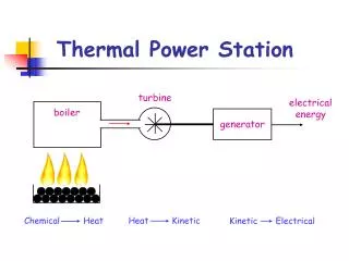
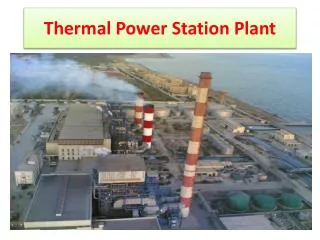
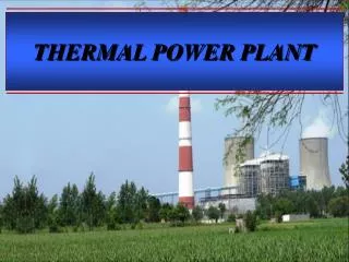
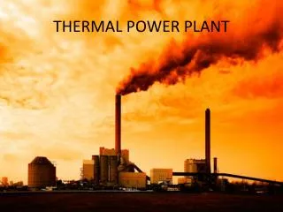
THERMAL POWER PLANT. Thermal Power Stations. Coal Fired Turbo alternators driven by steam turbine Oil Fired Crude oil OR Residual oil Gas Fired Fastest growing primary fuel, worldwide Combined cycle First stage - Gas turbine & Second stage - Steam Turbine Diesel Fired

E N D
Thermal Power Stations • Coal Fired • Turbo alternators driven by steam turbine • Oil Fired • Crude oil OR Residual oil • Gas Fired • Fastest growing primary fuel, worldwide • Combined cycle • First stage - Gas turbine & Second stage - Steam Turbine • Diesel Fired • IC Engine as prime mover • Standby power plants
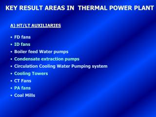
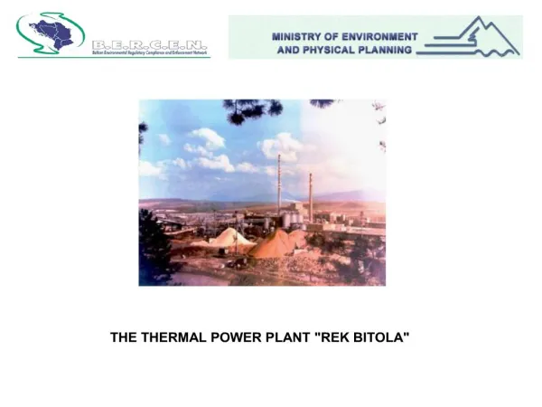
Selection of site • Nearness to load center • Supply of water • Availability of coal • Land requirement • Type of land • Labour supplies • Ash disposal • Distance from populated area
thermodynamic cycle • a type of steam engine involving a continuous cycle of vaporization of liquid and condensation back to liquid in a sealed system
merits & demerits • Merits: • Fuel used is cheaper • Cheaper installation cost comparatively • Cheaper production cost in comparison with diesel power plant • Can be installed at ay place irrespective of the existence of fuels unlike HEPP • Can be located near to load center unlike HEPP • Able to respond rapidly changing loads without difficulty • Steam engines and turbine can work under under 25% of over load continuously • Portion of steam raised can be used as process steam in various industries (paper mills, textile mills etc)
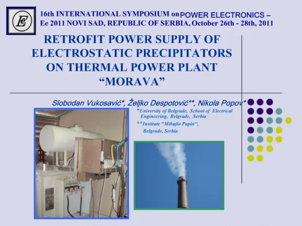
Merits & Demerits • Demerits: • High maintenance and operating cost • Pollution • Requirement of water in huge quantity • Handling of coal and ash is quite difficult • The plant cost increases with the increases in the operating temperature and pressure • Require long time for erection and put into action • Efficiency fall rapidly below 75% of full load
Components 1. Cooling tower 6. L.P turbine 11. H.P turbine 16. Coal pulverizer 21. Re-heater 2. Cooling water pump 7. Condensate pump 12. De-aerator 17. Boiler steam drum 22. Combustion 3. Transmission line 8. Surface condenser 13. Feed water heater 18. Bottom ash 23. Economizer 4. Transformer 9. I.P turbine 14. Coal conveyor 19. Super-heater 24. Air pre-heater 5. Generator 10. steam control valve 15. Coal hopper 20. Forced draught 25. Precipitator 26. Induced draught 27. Flue gas stack
Fuel & Ash Handling • Coal delivery: by trucks, wagons etc • Coal storage: Dead & Live storage • Crusher: coal is crushed to increase the area • Magnetic separator: removes impurities • Pulverizer: device to transform coal into fine powder • Ash pit: when fuel gets burnt, ash is collected in ash pit • Ash quenching: Ash is hot & dusty, hence needs to be quenched • Ash delivery: Quenched ash is taken using conveyors to the site
Furnace • A place where fuel is burnt • Encloses burning equipments Types • Grate fired: uses stationary or movable grates, suited for solid fuels. • Hand fired – uses stationary grate, small size plants, discontinuous process • Stoker fired – uses movable grate, medium & large size plants, continuous process . Over feed stoker: the fuel & air move are not in the same direction . Under feed stoker: the fuel & air move in the same direction • Chamber fired: suited for pulverized coal, liquid or gaseous fuels.
Boiler • Water tube boiler: DM water circulates through tubes & hot flue gases flow over them. • Less liable to explosion, produce high pressure steam, high efficiency, heating surface is large • Fire tube boiler: hot flue gases pass through the tubes which are surrounded by water. • Low cost, compact in size, heating surface is small, cannot produce high pressure steam, liable to explode, low efficiency Water tube boiler Fire tube boiler
Methods to improve thermal efficiency • Air pre-heater : • hot flue gases are used to pre-heat the air • pre-heats the air to be supplied to the furnace • Accelerates combustion • Economizer : • hot flue gases are used to heat the feed water • Improves efficiency • Reduces heat losses of flue gas • Reduces fuel consumption • Super heater : • Increases temperature of generated steam • High thermal efficiency • Avoids corrosion of turbine blades • Re-heaters : • Exhaust Steam from hp turbine is expanded • High turbine efficiency as the stages increase
CONDENSER Types • Surface condenser • No direct contact between steam & cooling water • Impure water can be used for cooling • Low running cost , high vacuum is obtained • Increased efficiency • Requires large space • High initial cost • Jet Condenser • Direct contact between steam & cooling water • Low initial cost • Compact • Low efficiency
Cooling towers • To reduce thermal pollution which occurs in open system • To cool water coming out of the condenser in a closed system • Water cooled, Air cooled cooling towers • Uses either natural draft or mechanical draft • Natural draft – utilizes buoyancy large space, high cost, less efficient • Mechanical draft uses fan, requires less space, improves efficiency Forced draft tower: blower type fan is located at the base of the tower & forces air into the tower Induced draft tower: fan is located at the top of the tower&pulls air through the tower. The fan induces hot moist air out the
Contd.. • Different types of cooling towers Induced draft
Draught • Draught : difference between absolute gas pressure & the ambient atmosphere pressure. If Patm< Pg as draught is positive & Patm>Pgasdraught is negative Types of Draught: Natural & Mechanical • Natural draft is subjected to outside air conditions and temperature of flue gases leaving the furnace, as well as the chimney height. All these factors make proper draft hard to attain and therefore make mechanical draft equipment much more economical. • Mechanical draft: reduces chimney height, independent of weather condition, easy control • Induced draft: This is obtained by simply using an induced draft fan (ID fan) which removes flue gases from the furnace and forces the exhaust gas up the stack. Almost all induced draft furnaces operate with a slightly negative pressure. • Forced draft: Draft is obtained by forcing air into the furnace by means of a fan (FD fan) and ductwork. Forced draft furnaces usually have a positive pressure & use under fed stoker firing. • Balanced draft: Balanced draft is obtained through use of both induced and forced draft. This is more common with larger boilers . The induced draft fan works in conjunction with the forced draft fan allowing the furnace pressure to be maintained slightly below atmospheric.
Governing system Functions: • To maintain constant shaft speed at all loads • To maintain constant steam flow through turbine • To maintain constant pass out and inlet/outlet steam pressures at all flows Methods of governing: • Throttle governing • Nozzle control governing • By-pass governing • Fly ball speed governing etc