Download
1 / 26
260 likes | 433 Vues
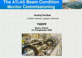
The ATLAS Beam Condition Monitor Commissioning. Andrej Gorišek J. Stefan Institute, Ljubljana, Slovenia. TWEPP Naxos, Greece 15-19 September 2008. Pixel. BCM-stations. Beam pipe. The ATLAS BCM collaboration. JSI, Ljubljana

E N D
The ATLAS Beam Condition Monitor Commissioning Andrej Gorišek J. Stefan Institute, Ljubljana, Slovenia TWEPP Naxos, Greece 15-19 September 2008 Pixel BCM-stations Beam pipe
The ATLAS BCM collaboration JSI, Ljubljana V. Cindro, I. Dolenc, A. Gorišek, G.Kramberger, B. Maček, I. Mandić, E. Margan, M. Zavrtanik, M. Mikuž CERN B. Demirkoz, D. Dobos, J .Hartert, H. Pernegger, P. Weilhammer Univ. of Applied Science, Wiener Neustadt E. Griesmayer, H. Frais-Kölbl, M. Niegl OSU, Columbus H. Kagan, S. Smith Univ. Toronto M. Cadabeschi, D. Tardif, W. Trischuk All you ever wanted to know about BCM: https://twiki.cern.ch/twiki/bin/view/Atlas/BcmWiki The ATLAS Beam Condition Monitor Commissioning
The ATLAS Beam Condition Monitor Commissioning The ATLAS Spectrometer AToroidal Lhc ApparatuS • The Inner Detector (ID): • closest to the interaction • efficient tracking of charged particles in a homogeneous axial magnetic field of 2 T • vertex reconstruction • electron identification capabilities in Transition Radiation Tracker (TRT) • consists of: Pixel Detector, SemiConductor Tracker (SCT) and TRT • Calorimeter system: • stop and measure energy of particles and distinguish between photons, electrons and hadronic jets • consists of: an electromagnetic (EM) calorimeter in the inner part, hadronic barrel calorimeter (Tile Calorimeter), hadronic end cap (HEC) and forward calorimeters (FCAL). • Muon Spectrometer: • independent tracking and momentum measurement of muons over large area • high pTmuon trigger • strong toroidal magnetic field of up to 4 T, generated by super-conducting air-core toroids,
The ATLAS Beam Condition Monitor Commissioning ATLAS Inner Detector
The ATLAS Beam Condition Monitor Commissioning Beam Accidents - Protection • ATLAS is furthest from injection – safest (?) • Passive protection: • ATLAS and CMS have Target Absorber Secondaries (TAS) collimators @ z=±18m:protecting inner triplet of quadrupols from secondaries produced in p-p collisions and Inner Detector from beam failures • Active protection: • Beam Interlock System (BIS): two redundant optical loops transporting BeamPermit signals – a logical AND of UserPermit signals provided by user systems (machine beam loss or beam position monitors, experiment BCMs, etc.) • Beam Condition Monitors (BCMs): contribute UserPermit signals to the BIS • If UserPermit is set to False optical loop is interupted BeamPermit removed, beam dump procedure initiated (beam is dumped within 3 turns ~270 μs) + no injection from SPS
The ATLAS Beam Condition Monitor Commissioning Beam Accidents • Most likely due to wrong magnet settings:~8000 magnets powered by ~1700 different electronic circuits • Single turn losses • @ injection from SPS • 450GeV + pilot bunch only (5 109 protons) – no danger to detectors • BCM will diagnose the loses and eventually prevent further false injections • Multi-turn losses • RF, magnet or collimator failure • TAS limits the damage to the innermost spectrometer • different time scales ranging from few turns (100’s of µs) to secondsthe most rapid due to warm dipole magnet (D1) failure closest to ATLAS interaction point t = ~5 turnsBCM has ~2 turns (~150 µs) to act
Simulation + past experience The ATLAS Beam Condition Monitor Commissioning Simulations of beam orbits with wrong magnet settings (D. Bocian) exhibit scenarios with beam scrapping TAS collimators LHC will circulate 2808 bunches per colliding beam, each bunch consisting of 1.1×10¹¹ protons at energy of 7 TeV – about 200-times more energy stored in beams compared to maximum value in previous accelerators like HERA or Tevatron. 20-30 Tevatron turns (misfiring of kicker magnet)
BCM background vs. Interaction Events The ATLAS Beam Condition Monitor Commissioning Time difference • Measurement every proton bunch crossing (every 25ns) • Distinguish between interactions and background (scraping of collimators, beam gas,...) requirement:better than 12.5 ns width+baseline restoration 6ns -6ns 2 detector stations, symmetric in z TAS (collimator) event: Δt=2z/c=12.5ns (ideally) Interaction: Δt = 0, 25, … ns
Detector module pCVD diamond sensors (10x10 mm2, contact 8x8mm2, 500m thick) Shown to withstand > 1015 p/cm2 Fast & short signal (FWHM~2ns, rise time<1ns) Large charge carrier drift velocity (107 cm/s)(operates with high drift field - 2 V/ m) Short charge lifetime (trapping) Very Low leakage current after irradiation Does not require detector cooling The ATLAS Beam Condition Monitor Commissioning Agilent MGA-62653 500Mhz (22 dB) Mini Circuits GALI-52 1 GHz (20 dB) BOTTOM pCVD diamond typical event
The ATLAS Beam Condition Monitor Commissioning Detector module assembly • ceramic module assembly scheme • increase modularity of BCM detector modules redundant HV connection alignment of diamond sensors in BCM detector module (at 45o = along beam direction)
BCM installed on Pixel detector The ATLAS Beam Condition Monitor Commissioning ATLAS Pixel BCM-stations Beam pipe
The 8 installed modules The ATLAS Beam Condition Monitor Commissioning MODULE 410 413 420 422 404 405 408 424 preferred polarity +1000V +1000V -1000V -1000V +1000V +1000V -1000V -1000V MPV [mV] 2.77 2.15 2.67 2.40 2.43 2.30 2.21 2.70 SNR 7.8 7.0 7.8 7.3 6.5 7.0 7.0 8.2
The ATLAS Beam Condition Monitor Commissioning BCM readout chain • analogue signals from BCM detector modules routed to region behind calorimeter (lower radiation levels – 10Gy in 10 years) where they are digitized by custom board based on NINO chip • signals from separate BCM detector modules are connected to separate NINO boards for electrical ground separation – minimize interference (grounds connected together close to detector modules) • optical signals are taken to electronics room (USA15) for processing by Vitrex-4 based FPGA board
NINO board The ATLAS Beam Condition Monitor Commissioning • amplifier-discriminator-TOT chip • developed for ALICE RPC ToF (CERN-MIC – F. Anghinolfi et al.) • radiation tolerant; IBM 0.25µm technology • LVDS output signal with rise time <1ns & jitter <25ps • 8 differential inputs (2 used on each board) • output signal width correlated to the input charge (min. detection threshold 10fC) • each BCM module connected to two NINO inputs in 1:11 ratio to increase NINO dynamic range • resulting two TOT digital signals from the NINO chip are further converted into optical signal with radiation tolerant laser diodes (Mitsubishi FU-427SLD-FV1).
The ATLAS Beam Condition Monitor Commissioning OPTO link board • 70m optical fibres from NINO boards (single mode fibers equipped with E2000 APC connectors) • receives 8 optical signals from 4 NINO boards (photo diode – Lightron LP3A4-SNC1) • PECL output to FPGA • NIM level monitor output
Backend - FPGA ML410 development board based on Virtex-4 8 RocketIO serial input/output channels sampling the received signals with frequency of 2.56 GHz real-time signal processing: signal arrival time, pulse width calculation RAM (circular buffer) stores 3×10⁶ last LHC bunch crossings (for “post mortem”) additional analysis: in-time and out-off time hits rates and trends of rates of each module coincidences for different combination of modules Use 2 boards and have them communicate channels arranged in redundant fashion (vertical modules to one and horizontal modules to another FPGA board for high gain channels and the opposite for low gain channels) The ATLAS Beam Condition Monitor Commissioning
The ATLAS Beam Condition Monitor Commissioning FPGA outputs • LHC Beam Abort:In case of beam failures, two redundant signals, indicating that beam conditions in the ATLAS Inner detector have reached the unacceptable levels, will be sent to the BIS resulting in beam abort. • ATLAS Detector Safety System (DSS)This hardware interlock system guards the experimental equipment and acts to prevent damages from any detected faulty situation. The BCM system has 4 electrical connection to DSS in order to send warnings or alarm signals. • ATLAS Detector Control System (DCS) • a PC, integrated into the ATLAS DCS system • monitor the temperature of detector modules and NINO electronics boards • control the high and low voltages • more sophisticated information (average rates, histograms, etc.), obtained from processed signals, available to ATLAS and LHC control through DCS PC connected via Ethernet to FPGA. • In case of a beam abort, all recent information from BCM, currently stored in ring buffer of FPGA, is transfered through DCS for post mortem analysis. • ATLAS Data Acquisition (DAQ) • FPGA also acts as a ROD. L1A signal will cause FPGA to send data to the ATLAS DAQ system through standard optical S-link. • ATLAS LVL1 trigger • information to the ATLAS LVL1 trigger in a form of 9 (temporarily 6) bits for topologically interesting events
BCM QA QA of all modules through production cycle Raw sensor characterization / ceramic module I/V, CCD Module performance Noise Signal from 90Sr Thermal cycling: 10 cycles from -25oC to 45oC Infant mortality – 12h @ 80oC Resulting S/N from 6.5 to 8.2 for perpendicular incidence The ATLAS Beam Condition Monitor Commissioning
SPS beam test setup The ATLAS Beam Condition Monitor Commissioning 4 tracking modules – Si-strip(4 XY point along particle trajectory) trigger scintillators 180GeV/c beam BCM modules
Analog signals – surface uniformity all modules tested in beam-test setup: signal & noise performance surface uniformity The ATLAS Beam Condition Monitor Commissioning signal noise size of diamond sensor (tilted 45o) signal uniform over surface
Efficiency and noise rate The ATLAS Beam Condition Monitor Commissioning • SNR after NINO digitization ~7.2 • contribution of NINO (no input) to s ~29mV compatible with decrease in SNR (compatible with SNR before NINO normalized to 45o ~10)
Efficiency vs. noise occupancy The ATLAS Beam Condition Monitor Commissioning usable? NINO digital circuit features amplifier discriminator and TOT measurement • by changing the discriminator threshold efficiency and noise rate (occupancy) changes • noise occupancy is scaled noise rate to 25 ns interval • efficiency of system up to digital circuit (NINO) triggering on an incident MIP (in scintillators) Efficiency @ noise occup. 99.5% 10-6 99% 2 10-8 97.5% 10-9 95% 5 10-12
Timing resolution The ATLAS Beam Condition Monitor Commissioning Time difference between two detectors: • RMS~500 ps per detector (end of read out chain) • practically all events inside [-2ns,2ns]
The ATLAS Beam Condition Monitor Commissioning Noise performance of installed modules Gaussian noise observed on all channels All modules in range between 50mV and 70mV
The ATLAS Beam Condition Monitor Commissioning ATLAS – “First Event” 2 109 protons in one beam on colimator
Summary The ATLAS BCM was constructed using radiation hard pCVD diamonds back to back ”double decker” configuration at 45o towards the beam Test beam and on-the-bench result indicate operable system S/N, risetime, pulse-width,... meet the design criteria efficiency/noise occupancy reasonable ATLAS BCM status (commissioned!): FE installed in January 2007 NINO TOT electronics installed in spring 2008 – noise performance adequate FPGA Xilinx Vitrex-4 based back-end – running in common ATLAS framework The ATLAS Beam Condition Monitor Commissioning