Download

1 / 23
230 likes | 257 Vues
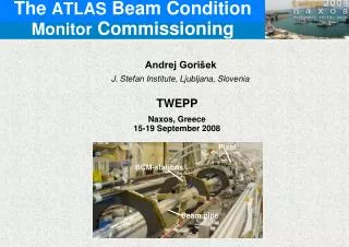
This document outlines the commissioning process of Luminosity Monitors for the MICE Collaboration Meeting held on March 26-24, 2010. The purpose of the Luminosity Monitors is to measure particle rates near the target, validate particle production, compare rates with other counters along the beamline, and aid in beam commissioning for improved efficiency. The installation, design, positioning, and commissioning details are discussed, along with preliminary data analysis and comparison to simulations.

E N D
Luminosity Monitor Commissioning MICE Collaboration Meeting 26 24 March 2010 Paul Soler, David Forrest Danielle MacLennan
Purpose of Luminosity Monitors • Luminosity monitor to determine particle rate close to target and extract protons on target as function of depth – independent of beam loss monitors. • Luminosity monitor will record the number of particles crossing 4 scintillators for every spill – can build up high statistics to validate particle production in target. • By having a small plastic filter we can also reduce low energy protons – some sensitivity to proton energy. • Can be used to compare particle rates close to target (luminosity monitor measures mainly protons and pions) with other counters along beamline (GVA1, TOF0, CKOV, TOF1 and FBPM counters which measure pions, muons, electrons) – validate beamline simulations • For this reason, the luminosity monitor will be very useful for beam commissioning LM Commissioning, MICE VC, 25 February 2010
Luminosity Monitor Design • Final design of luminosity monitor: Cuts off: protons ~500 MeV/c pions ~150 MeV/c (6 mm thick) (6 mm thick) Beam LM Commissioning, MICE VC, 25 February 2010
Luminosity Monitor Design • Final design of luminosity monitor: Cuts off: protons ~500 MeV/c pions ~150 MeV/c Beam LM Commissioning, MICE VC, 25 February 2010
50 mm Photomultipliers • PMTs: Hamamatsu H5783P • 0.8 ns rise time • ~1x10⁶ gain • Only need to provide <15V to power PMT • Readout: use NIM coincidence units and count three channels using VME scalers already in DAQ High rate capability with 20 ns coincidence gate LMC-12 Discriminator set at 500 mV for all channels LMC-1234 If rate still an issue, can make more shielding LMC-34 LM Commissioning, MICE VC, 25 February 2010
Installation of Luminosity Monitors • Installation of Luminosity Monitor: 12-15 January 2010 • Many thanks to Willy, Jeff Barber, Daresbury cabling team • Installed RG58 cables (8 x 80 m between ISIS vault and MICE control room) • Stand modified for luminosity monitor and installed in vault LM Commissioning, MICE VC, 25 February 2010
Installation of Luminosity Monitors • Position of luminosity monitor:10 m from target at 25o. LM Commissioning, MICE VC, 25 February 2010
Commissioning Luminosity Monitors • Commissioning was performed in 12-15 January and 7 February with a dedicated MICE run • Purpose: define detector HV conditions, determine discriminator levels, synchronise with ISIS signals, set-up scalers, run at different beam loss levels to test correlation with LM detectors. • Unfortunately, one PMT was dead when installed in January so this also had to be replaced on 7 Feb • Gate initially 5 ms but now gate is 3.23 ms (same as trigger) LM Commissioning, MICE VC, 25 February 2010
Commissioning Luminosity Monitors • Runs performed 7 February (many thanks to Terry, Pierrick, Adam and Vassil for help during shift!) LM Commissioning, MICE VC, 25 February 2010
Preliminary analysis of data • Adam Dobbs provided the analysis of the beamloss data • Preferred method is to integrate beam loss signal in sector 7 • Unfortunately, this method at the moment produces unreliable results below a beamloss of ~0.30 V • The method can be improved by subtracting background before and after beamloss signal but analysis not implemented yet • Instead, removed beamloss < 0.30V LM Commissioning, MICE VC, 25 February 2010
Preliminary analysis of data LM Commissioning, MICE VC, 25 February 2010 Removed unreliable Beamloss
Preliminary analysis of data LM Commissioning, MICE VC, 25 February 2010 Removed unreliable Beamloss
Preliminary analysis of data LM Commissioning, MICE VC, 25 February 2010 Removed unreliable Beamloss
Preliminary analysis of data • Summary of results: • LMC-12: 1955 particles per V.ms / 4 cm2 • LMC-34: 2086 particles per V.ms / 9 cm2 • LMC-1234: 889 particles per V.ms / 4 cm2 • Beam-loss monitor calibrations: • Assume beamloss calibration of 3.5x10⁻¹⁴ V.s/pot at 9 ms. • LMC-12: 1.71x10⁻⁸ particles/(pot . cm2) • LMC-34: 0.81x10⁻⁸ particles/(pot . cm2) • LMC-1234: 0.77x10⁻⁸ particles/(pot . cm2) BLM calibrations as function of KE (from Dean Adams): LM Commissioning, MICE VC, 25 February 2010
Comparison to simulations • Simulations for the old target (10x1 mm2) with different geometry using MARS and GEANT4 at 800 MeV yield: • MARS simulation: • GEANT4 simulation: • Good agreement with observed rate for MARS, GEANT4 simulations and unshielded detectors (LMC-12). • Even though these simulations were done using the old target, the average material in target is very similar: • New target: p(3.02-2.32)=11.7 mm2 Beam LM Commissioning, MICE VC, 25 February 2010 Beam
New simulations • We are running new simulations using G4Beamline • Set up cylindrical target (R=3mm,r=2.3mm), and two detectors 100x100cm2, separated by 15 cm plastic at 10 m and 25o angle. Include 6 mm thick steel from target enclosure Target Beam pipe Detectors LM Commissioning, MICE VC, 25 February 2010
New simulations • Only select particles within acceptance of detectors (100x100cm2 at 10 m) and kill all other particles • Test that we don’t kill valid particles by changing kill volumes (yellow volumes) Target Proton Beam LM Commissioning, MICE VC, 25 February 2010
Comparison hadronic models • Only select particles within acceptance of detectors (100x100cm2 at 10 m) and kill all other particles • First run with QGSP hadronic model Unshielded detectors Shielded detectors QGSP QGSP LM Commissioning, MICE VC, 25 February 2010
Comparison hadronic models • Only select particles within acceptance of detectors (100x100cm2 at 10 m) and kill all other particles • Now run with QGSP_BERT (QGSP+Bertini cascade model) for comparison Unshielded detectors Shielded detectors QGSP_BERT QGSP_BERT LM Commissioning, MICE VC, 25 February 2010
Comparison hadronic models • Compare number protons crossing unshielded detector (104 cm2) for different hadronic models (up to a factor 2): LM Commissioning, MICE VC, 25 February 2010
Comparison target geometry • Compare number protons crossing unshielded detector (104 cm2) for the two target geometries to understand normalisation • Compare new target (cylinder with outer radius 3 mm and inner radius 2.3 mm) with old target (10 mm x 1 mm) New Old • Volume material in each target is very similar (assume depth inside beam=10mm): • Old target: 10x1x10 mm3 • New target: p(3.02-2.32)x10=116.7 mm3 LM Commissioning, MICE VC, 25 February 2010
Comparison target geometry • Compare number protons crossing unshielded detector (104 cm2) for two target geometries (using QGSP_BIC) • There is a factor of ~8 difference in normalisation, but we need to take into account that old target has 10 mm thickness • New target has variable thickness due to geometry of cylinder (effective average thickness 1.945 mm=116.7/60) • Need to correct for number protons that actually interact with target to correct for normalisation, but can estimate: LM Commissioning, MICE VC, 25 February 2010 (agreement not as good!)
Conclusion • Luminosity Monitors have been installed in ISIS vault and are working properly • MOM now has instruction sheet to operate detectors • LM data scales very well with beam loss data • Calculation of protons on target from old simulation (for the old target) agrees with data from LM • Normalisation of new simulations for cylindrical target does not agree so well and work is still in progress to understand this. • Need to improve method for beamloss calculation at low beamloss (<0.03 V) • Once further verification of scalar data and better understanding normalisation in simulations, we can use the LM scalar data to determine protons on target, independent of beamloss data LM Commissioning, MICE VC, 25 February 2010