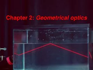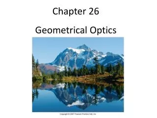
Chapter 26 Geometrical Optics
1.59k likes | 2.3k Vues
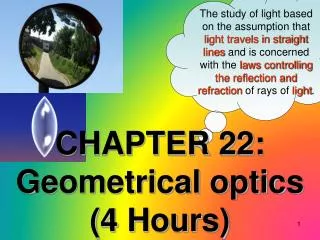
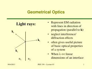
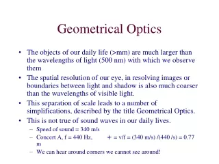
Chapter 26 Geometrical Optics. The Reflection of Light. If a stone is dropped into a pond, circular waves emanate from the point where it landed. Rays, perpendicular to the wave fronts, give the direction in which the waves propagate.

Chapter 26 Geometrical Optics
E N D
Presentation Transcript
Chapter 26 Geometrical Optics
The Reflection of Light If a stone is dropped into a pond, circular waves emanate from the point where it landed. Rays, perpendicular to the wave fronts, give the direction in which the waves propagate.
As one moves farther from a point wave source, the wave fronts become more nearly flat.
Reflection • Reflection occurs when light bounces off a surface. • There are two types of reflection:
1. Specular reflection: Off a shiny surface 2. Diffuse reflection: Off a rough surface .
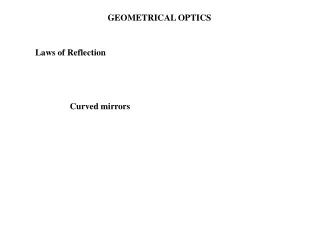
The Law of “REFLECTION” The Law of Reflection states that- " the angle of incidence (incoming ray) equals the angle of reflection (outgoing ray)" The law works for FLAT, PLANE surfaces only. The angles are measured from a perpendicular line to the surface called a NORMAL. NORMAL
A ray of light reflects from a plane mirrorwith an angle of incidence of 37o. If themirror is rotated by an angle of 5o, throughwhat angle is the reflected ray rotated?
Sample Problem: Standing 2.0 m in front of a small vertical mirror, you see the reflection of your belt buckle, which is 0.70 m below your eyes What is the vertical location of the mirror relative to the level of your eyes?
Sample Problem: Standing 2.0 m in front of a small vertical mirror, you see the reflection of your belt buckle, which is 0.70 m below your eyes What is the vertical location of the mirror relative to the level of your eyes?
Forming Images with a Plane Mirror Light reflected from the flower and vase hits the mirror. Obeying the law of reflection, it enters the eye. The eye interprets the ray as having had a straight-line path, and sees the image behind the mirror.
Plane Mirror Suppose we had a flat , plane mirror mounted vertically. A candle is placed 10 cm in front of the mirror. WHERE IS THE IMAGE OF THE CANDLE LOCATED? mirror On the surface of the mirror? Behind the mirror? Object Distance, Do = 10 cm Same side as the object?
Plane Mirror Suppose we had a flat , plane mirror mounted vertically. A candle is placed 10 cm in front of the mirror. WHERE IS THE IMAGE OF THE CANDLE LOCATED? mirror Virtual Image Object Distance, Do = 10 cm Image Distance, Di = 10 cm Do = Di, and the heights are equal as well
Properties of Mirror Images Produced by Plane Mirrors: • A mirror image is upright, but appears reversed right to left. • A mirror image appears to be the same distance behind the mirror that the object is in front of the mirror. • A mirror image is the same size as the object.
Virtual Images Virtual Images are basically images which cannot be visually projected on a screen. If this box gave off light, we could project an image of this box on to a screen provided the screen was on the SAME SIDE as the box. You would not be able to project the image of the vase or your face in a mirror on a screen, therefore it is a virtual image. CONCLUSION: VIRTUAL IMAGES are ALWAYS on the OPPOSITE side of the mirror relative to the object.
Ray tracing: plane mirror Construct the image using two rays.
Ray tracing: plane mirror Construct the image using two rays.
A corner reflector reflects light parallel to the incident ray, no matter the incident angle.
26-3 Spherical Mirrors A spherical mirror has the shape of a section of a sphere. If the outside is mirrored, it is convex; if the inside is mirrored, it is concave.
Spherical mirrors have a central axis (a radius of the sphere) and a center of curvature (the center of the sphere).
Spherical Mirrors – Concave & Convex Also called DIVERGING mirror Also called CONVERGING mirror
Parallel rays hitting a spherical mirror come together at the focal point (or appear to have come from the focal point, if the mirror is convex).
Converging (Concave) Mirror A converging mirror is one that is spherical in nature by which it can FOCUS parallel light rays to a point directly in front of its surface. Every spherical mirror can do this and this special point is at a “fixed” position for every mirror. We call this point the FOCAL POINT. To find this point you MUST use light from “infinity” Light from an “infinite” distance, most likely the sun.
Converging (Concave) Mirror Since the mirror is spherical it technically has a CENTER OF CURVATURE, C.The focal point happens to be HALF this distance. Note ‘C’ is the radius We also draw a line through the center of the mirror and call it the PRINCIPAL AXIS.
26-4 Ray Tracing and the Mirror Equation • We use three principal rays in finding the image produced by a concave mirror. • The parallel ray (P ray) reflects through the focal point. • The focal ray (F ray) reflects parallel to the axis. • The center-of-curvature ray (C ray) reflects back along its incoming path.
26-4 Ray Tracing and the Mirror Equation These three rays are illustrated here.
Ray Diagram A ray diagram is a pictorial representation of how the light travels to form an image and can tell you the characteristics of the image. C object f Principal axis Rule One: Draw a ray, starting from the top of the object, parallel to the principal axis and then through “f” after reflection.
Ray Diagram A ray diagram is a pictorial representation of how the light travels to form an image and can tell you the characteristics of the image. C object f Principal axis Rule One: Draw a ray, starting from the top of the object, parallel to the principal axis and then through “f” after reflection.
Ray Diagrams C object f Principal axis Rule Two: Draw a ray, starting from the top of the object, through the focal point, then parallel to the principal axis after reflection.
Ray Diagrams C object f Principal axis Rule Three: Draw a ray, starting from the top of the object, through C, then back upon itself. THEY INTERSECT What do you notice about the three lines? The intersection is the location of the image.
Ray Diagram – Image Characteristics C object f Principal axis • After getting the intersection, draw an arrow down from the principal axis to the point of intersection. Then ask yourself these questions: • Is the image on the SAME or OPPOSITE side of the mirror as the object? • Same, therefore it is a REAL IMAGE. • Is the image ENLARGED or REDUCED? • Is the image INVERTED or RIGHT SIDE UP?
26-3 Spherical Mirrors For a convex mirror, the focal length is negative, as the rays do not go through the focal point. The opposite is true for a concave mirror.
26-3 Spherical Mirrors We have made the assumption here that the rays do not hit the mirror very far from the principal axis. If they do, the image is blurred; this is called spherical aberration, and can be remedied by using a parabolic mirror instead.
26-3 Spherical Mirrors When the Hubble Space Telescope was first launched, its optics were marred by spherical aberration. This was fixed with corrective optics.
26-4 Ray Tracing and the Mirror Equation The process is similar for a concave mirror, although there are different results depending on where the object is placed.
26-4 Ray Tracing and the Mirror Equation This image shows how these three rays are used to find the image formed by a convex mirror. The image is located where the projections of the three rays cross. The size of the image can also be determined.
26-4 Ray Tracing and the Mirror Equation We derive the mirror equation using the ray diagrams:
26-4 Ray Tracing and the Mirror Equation Using the similar triangles and the fact that f = ½ R, we get the mirror equation: Here, do is the distance from the mirror to the object, di is the distance from the mirror to the image, and f is the focal length.
Mirror/Lens Equation Assume that a certain concave spherical mirror has a focal length of 10.0 cm. Locate the image for an object distance of 25 cm and describe the image’s characteristics. 16.67 cm What does this tell us? First we know the image is BETWEEN “C” & “f”. Since the image distance is POSITIVE the image is a REAL IMAGE. Real image = positive image distance Virtual image = negative image distance What about the size and orientation?
Sample Problem: Calculate the magnification for the previous problem.
Here are the sign conventions for concave and convex mirrors:
Sample Problem Assume that a certain concave spherical mirror has a focal length of 10.0 cm. Locate the image for an object distance of 5 cm and describe the image’s characteristics. -10 cm Characteristics? • VIRTUAL (opposite side) • Enlarged • Upright 2x
Refraction Refraction is based on the idea that LIGHT is passing through one MEDIUM into another. The question is, WHAT HAPPENS? Suppose you are running on the beach with a certain velocity when you suddenly need to run into the water. What happens to your velocity? IT CHANGES!
Refraction • Refraction is the movement of light from one medium into another medium. • Refraction cause a change in speed of light as it moves from one medium to another. • Refraction can cause bending of the light at the interface between media.
26-5 The Refraction of Light Light moves at different speeds through different media. When it travels from one medium into another, the change in speed causes the ray to bend.
Refraction What EXACTLY is light doing when it reaches a new medium? We don’t want you to think ALL of the light refracts. Some of the light REFLECTS off the boundary and some of the light REFRACTS through the boundary. Angle of incidence = Angle of Reflection Angle of Incidence > or < the Angle of refraction depending on the direction of the light