Download
1 / 18
180 likes | 563 Vues
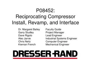
P08452: Reciprocating Compressor Install, Revamp, and Interface. Dr. Margaret Bailey Faculty Guide Garry Studley Project Manager Dave Rigolo Lead Engineer Alec Jarvie Industrial Systems Engineer Chris Neitz Computer Engineer Kiernan French Mechanical Engineer.

E N D
P08452: Reciprocating Compressor Install, Revamp, and Interface Dr. Margaret Bailey Faculty Guide Garry Studley Project Manager Dave Rigolo Lead Engineer Alec Jarvie Industrial Systems Engineer Chris Neitz Computer Engineer Kiernan French Mechanical Engineer
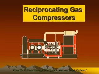
Original N30NL-4 Description • 6 Stage Vertical Reciprocating Air Compressor • 30 CFH at 3000 PSIG • Positive Displacement • Designed for Automated Operation • Used on Naval Ships • Destroyers and Carriers • Original Cost/Actual Value • $400,000/$800,000
Project Description • Installation at RIT • 09-2329 Engine Test Cell • Redesign of Machine • 6 Stages -> 2 Stages • 3000 PSIG -> ~100 PSIG • 75 HP -> ~25 HP • Consider future uses • Interface Setup • Future data acquisition
Safety Considerations Equipment List Trainings 70-95°F Maintenance Capabilities 24”-35” Access Space 30-45 ft2 Storage Space Tooling List < 40 lbs. Manual Lifting 150-225 lbs. Assisted Lifting Installation of Compressor 8-19 Weeks from 12/3/07 Acoustic Levels 75-100 dB Vibrations 0.1-1.0 g/s 0 injuries Room Structural Load =15,000 lbs (nf = 2.0) Compressor Revamp 6 to 2 Stages 25-37.5 hp 100+/-10 psi 45-90.3 A Future Use Considerations Modifiable Interface Modifiable DAQ Variables Timeline for Projects Allowances for Projects Dresser-Rand Involvement Weekly Teleconference Meetings Bi-weekly Reviews Operation and Maintenance: Student Manual High Level Customer Needsand Engineering Specs
Relationships of Sub-functions 3 2 4 Create a functional interface to log and trend data Safely install compressor 1 1 – Installation and interface relate via the installation of a suitable computer workstation 2 – Interface and revamp relate through the documents both sub functions will produce for future teams to use 3 – Revamp and installation are related through the creation of a safe environment suitable for the revamp of the compressor 4 – All sub-functions work together to provide a safe, solid, and functional foundation for future teams to pursue further revamp and fault detection projects
Safety Considerations • Vibration shutoff switch • due to excessive vibrations • Emergency kill switch • 2 e-stops to ensure safe exit from room • Lock-out Tag-out Panel • Prevent electrocution and pinch hazards • Safety equipment • Eye, Ear, Hand and Foot Protection • Fire Hazards • 2 fire extinguishers for ABCD type fires • Signage • Warnings, Hazards, and Exits Clearly marked
Concept Description: Installation • Test Cell Layout • Installation procedure and preparations • Boulter Rigging Corporation: Used to transport and place machine • Necessary Supplies: Storage Rack, Workbench, Desk, Tools, Tool Chest Top View of Test Cell with Components and Locations Section A-A: Basement view of Test Cell and Compressor Position
Concept Description: Mounting • Primary design intent: • Reduce amount of vibrations transferred to floor and surrounding building • Maintain machine position • Distribute weight on floor 12 Heavy duty spring mounts are to mounted along he perimeter of the machine using existing mounting holes. Concrete anchors will attach the mounts to the floor. • Spring Mount Specifications • Highest vibration isolation from floor (Need 5.4 Reduce Vibs Impact) • High deflection if needed to absorb serve vibrations (Need 3.4 Scale Down Vibs) • Distributes weight to 12 21in^2 areas on floor (Need 1.2 Safety, Structural) • High weight capacity (13200lbs) (Need 1.2 Safety, Structural) • Anchoring to floor (Need 1.1 Safety, Install) • Reasonable Price and Labor 12X
Concept Description: Revamp • Power • Reduced to 25 HP (Calculated) • Electrical • 37.5 Amps (Calculated) • Cooling • 17°F DT in Open Loop Cooling (Fresh Water) • Exhaust Considerations
Concept Description: Interface • System to acquire and trend data from the compressor • Temperature • Pressure • Flow • Crank angle • Vibration • Valve timing • LabView chosen as program to interconnect interface and DAQ • DAQ device will be purchased from National Instruments
Concept Design of Interface • Initial design • Measurements organized by stage and type • Includes options to change sampling time, save files
High Risk Assessment • Mitigated • Sound (D-R Data, Dissipation Experiment) • Vibration (Spring-Action Damping Mounts) • Budget (Coordination between D-R and RIT) • Remaining • Structural Load (Consultant Lead Time) • Formula SAE Team (Exit Test Cell 09-2329)
Current State of Design • Designs meet all customer needs • Designs meet engineering specifications except for: • Structural load capabilities not confirmed • On target to meet project budget pending: • Costs for Electrician and Structural Consultant • Schedule: • Only possible issue is compressor arrival due to consultant lead time • Mitigations: • Environmental effects from machine (Heating and Sound) • Lifting and access specifications for motor removal
Student VersionOperation and Maintenance Manual • Auxiliary Document, attached to the N30NL-4 “Maintenance Manual” • Starting Guide for Future Project Teams • Safety Considerations • Procedures • Engineering Details
Installation and Interface Design Timeline Installation, Revamp Designs, and Interface Developments