5. Application Examples
5. Application Examples. 5.1. Programmable compensation for analog circuits (Optimal tuning) 5.2. Programmable delays in high-speed digital circuits (Clock skew compensation) 5.3. Automated discovery – Invention by Genetic Programming (Creative Design) 5.4. EDA, analog circuit design

5. Application Examples
E N D
Presentation Transcript
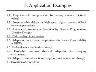
5. Application Examples 5.1. Programmable compensation for analog circuits (Optimal tuning) 5.2. Programmable delays in high-speed digital circuits (Clock skew compensation) 5.3. Automated discovery – Invention by Genetic Programming (Creative Design) 5.4. EDA, analog circuit design 5.5. Adaptation to extreme temperature electronics (Survivability by EHW) 5.6. Fault-tolerance and fault-recovery 5.7. Evolvable antennas (In-field adaptation to changing environment) 5.8. Adaptive filters (Function change as result of mission change) 5.9 Evolution of controllers 1
Automated synthesis of digital circuits Evolution at High Specification Level hardware Description Language (using e.g. VHDL) module.0 ls_comp.1 ls_pin.1 ls_action.2 COMPILE SIMULATE ls_comp.0 comp.3 cond_action.1 SYNTHESIS Evolution at Low Specification Level Gate Diagram of FPGA (using Configuration Bits) Chromosome Representation SIMULATE DOWNLOAD Implementation Level Programmable Logic Device Circuit Specification: - At Block level, using a hardware description language, such as VHDL, is used as the genetic encoding of the circuit. The automated synthesis optimizes the HDL code, compiles and downloads into a Programmable Logic Device. - At the logic gate level, the configuration bits in the programmable device are used as the genetic encoding of the circuit. The automated synthesis optimizes the configuration bits and download into a Programmable Logic Device. Circuit Evaluation: The evaluation of the digital design is done by simulation or by downloading the configuration bits of the candidate design into a Programmable Logic Device. The design performance is evaluated by using the input-output mapping for a combinatorial circuit and by tracing the states sequence or the state transition paths for a sequential circuit.. Achievements: Early Successful automated synthesis of digital circuits, such as 6-in MUX (25 gates) [KIT96], a 4-bit comparator (23 gates) [HIG96], and a sequential adder (50 gates) [ZEB96]. - Automated synthesis of an HDL-program representing a circuit wih 8 control states (using 100 gates) [HEM96]. More recently: Cartesian Genetic Programming Automated synthesis of HDL code (r0.0) module -> K_MOD name list_comp list_pin list_action (r1.0) name -> K_NAME (r2.0) list_comp -> comp (r20.3) comp -> K_INSTRIN inst_name HDL code for ant control Automated synthesis of Logic Gates A0 001110010001111010101010000 A1 OUTPUT 1: A>=B 0: A< B Chromosome Representation B0 B1 2-channel 2-bit comparator 2
Evolution of digital gates at transistor level • New digital cells, for specific applications, e.g. extreme temperatures, radiation, very low voltage, new component devices (e.g. 4-gate transistor), etc. • Analog characteristics of sub-micron, high-speed 3
Coverage of functional space • Check design corners, not only typical values. Many tests for same circuit. Vdd, temperature are most common, some are application specific. • Need for comprehensive testing to ensure that evolved solutions cover the intended operational space; • Contrary to conventional design, no assumptions on the circuits’ performance outside the points tested during evolution can be reliably made. 4
Combinations of input logic levels • Candidate logic circuits should be tested in transient analysisfor all possible transitions of combinations of input levels; • For example, a circuit may respond well as an AND gate to input combinations of levels 0-0, 0-1, 1-0, 1-1. However, it may have a long switching time when inputs 1-1 following 0-0 - and not 1-0 as above, which is not tested in the simple scheme; • Increased transient analysis: seven input configuration cases opposed to four. 5
Fan-out • Loading problem: preliminary experiments showed that evolved circuits were not able to drive similar circuits; • Problem: Input/Output impedance of circuit to be evolved is not known in advance; • Use of domain knowledge may help: in the case of logic gates we constrain the circuit inputs to connect only to transistor gate terminals, opposed to source or drain: increase input resistive impedance. 6
Time constants • Timescale Problem: preliminary evolved logic gates changed their behavior over a "frequency range“, i.e. different responses when tested with slow/DC signals and faster input changing signals; • Testing in micro-seconds timescale → Transient solutions; • Testing in seconds timescale → Slow gates; • Solution: extend the transient analysis duration to avoid transient solutions while keeping the transient analysis step small enough to assess the gate speed. 7
Testing to design corners Testing Design Corners through Mixtrinsic Evolution: • Robustness to changes in model accuracy, temperature and power supply (Vdd); • Have only the final evolved circuits tested to all design corners ( 10% variations of Vdd, temperatures from –20oC to 200oC, slow/fast transistor models) or • Accelerate evolution via mixtrinsic evolution, biasing small fraction of the population to be tested for corners. 8
Silicon validation results • Several circuits evolved at transistor level and then fabricated on a prototype ASIC on a HP 0.5 micron process; • Circuit representation: the chromosome encodes the circuit topology (MOS transistor connections) and the transistors’ sizes (width and length); • Number of components was imposed, or limited to maximum 8; • Most experiments used populations of 40 individuals and a number of 400 generations. 9
Silicon validation results In1 In2 Out NAND response Evolved circuit NOR response 10
Operability in Cascaded Designs Error Detection Adder fabricated in silicon Silicon results 11
Switching Speed Tests • Gates were evolved to work at only 1kHz but could actually be switched at higher frequencies; • Testing maximum speed of NAND gate for 1pF load: in simulation the NAND functionality does not work for a switching period of 2s, while in silicon the switching time can be decreased to less than 1s. 12
Switching Speed Tests Simulation Silicon NAND gate: Load 1pF, 2us switching time The inputs were applied in the following sequence: 00→11→01→11→10→11→00, to test all possible transitions 13