CI590 Redundant FieldBus Interface Overview
110 likes | 221 Vues
Learn about the CI590 module parameters and LED details in the AC500 High Availability System. Includes 16 digital configurable channels, fast counter modes, and error indication features.

CI590 Redundant FieldBus Interface Overview
E N D
Presentation Transcript
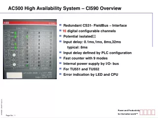
AC500 High Availability System – CI590 Overview • Redundant CS31- FieldBus – Interface • 16 digital configurable channels • Potential isolated • Input delay: 0.1ms,1ms, 8ms,32ms typical: 8ms • Input delay defined by PLC configuration • Fast counter with 9 modes • Internal power supply by I/O- bus • For TU551 and TU552 • Error indication by LED and CPU
AC500 High Availability System – CI590 Overview CI590 Module Parameters
AC500 High Availability System – CI590 Overview CI590 LED Details PWR LED ON CI590 Power ON OFF CI590 Power OFF PWR CS31-A S- ERR I/O ERR RUN A RUN B SYNC ERR CS31-B
SYNC ERR PWR CS31-A CS31-B S- ERR I/O ERR RUN A RUN B AC500 High Availability System – CI590 Overview CI590 LED Details Xxx ERR Led ON PLCs have sent different configurations OFF - Blink slow Switchover has happened Blink fast CI590 is not parameterized
SYNC ERR PWR CS31-A CS31-B S- ERR I/O ERR RUN A RUN B AC500 High Availability System – CI590 Overview CI590 LED Details CS31-A / B LEDs ON PLC A/B is available OFF PLC A/B is not available Blink No bit life from PLC A/B
SYNC ERR PWR CS31-A CS31-B S- ERR I/O ERR RUN A RUN B AC500 High Availability System – CI590 Overview CI590 LED Details SUM ERROR Same functioning as DC551 I/O BUS COMMUNICATION
SYNC ERR PWR CS31-A CS31-B S- ERR I/O ERR RUN A RUN B AC500 High Availability System – CI590 Overview CI590 LED Details RUN A / B LEDs PLC B PLC A OFF ON PLC A Primary OFF ON PLC B Primary Two primary information received. Primary PLC selected is the one corresponding to LED ON. ON Blink } ON Blink OFF } No primary information received. Primary PLC selected is the one corresponding to LED blinking. Blink OFF Blink
CPU A / B – COM1 CS31 Connection 9 7 6 5 8 3 2 1 4 Term. P RxD/TxD-P 120 Ω RxD/TxD-N Term. N RTS TxD CPU A / B - OUT SGND RxD CTS AC500 High Availability System – CS31 Bus Connection COM1 OF THE AC500 CPU
CI590 1.0 4.0 1.0 2.1 3.0 1.1 R21 R11 C8 C0 4.1 1.1 2.1 3.1 1.2 R22 R12 C9 C1 4.2 1.2 2.2 3.2 1.3 B2 1 B1 1 C10 C2 4.3 1.3 2.3 3.3 1.4 B1 2 B2 2 C11 C3 1.5 4.4 1.4 2.4 3.4 FE C12 FE C4 1.6 Xxx ERR PWR 4.5 1.5 2.5 3.5 B1 1 B2 1 1.7 C13 C5 ADDR x10 CS31-2 CS31-1 4.6 1.6 2.6 3.6 1 2 3 4 1.8 B2 2 B1 2 C14 C6 S- ERR 0 5 4.7 1.7 2.7 3.7 1.8 9 8 7 6 FE C15 FE C7 I/O ERR 1.8 2.8 3.8 4.8 ADDR x1 UP UP UP UP 1 2 3 4 RUN2 1.9 2.9 3.9 4.9 RUN1 0 5 ZP ZP ZP ZP 9 8 7 6 2.0 2.1 2 x CS31 16DC Input 24VDC Output 24VDC 0.5A CH-ERR3 UP 24VDC 200W CH-ERR4 2.2 2.3 2.4 2.5 2.6 2.7 2.8 2.8 1.0 2.0 3.0 4.0 1.1 2.1 3.1 4.1 1.2 2.2 3.2 4.2 1.3 2.3 3.3 4.3 1.4 2.4 3.4 4.4 1.5 2.5 3.5 4.5 1.6 2.6 3.6 4.6 1.7 2.7 3.7 4.7 1.8 2.8 3.8 4.8 1.8 2.8 3.8 4.8 AC500 High Availability System – CS31 Bus Connection LINE A / B OF THE CI590 R1 R2 B1 B2 FE B1 B2 FE UP ZP R1 R2 B1 B2 FE B1 B2 FE UP ZP CPU B - IN CPU A - IN CPU B - OUT CPU A - OUT Connection Line B Connection Line A
CI590 1.0 4.0 1.0 2.1 3.0 1.1 R21 R11 C8 C0 4.1 1.1 2.1 3.1 1.2 R22 R12 C9 C1 4.2 1.2 2.2 3.2 1.3 B2 1 B1 1 C10 C2 4.3 1.3 2.3 3.3 1.4 B1 2 B2 2 C11 C3 1.5 4.4 1.4 2.4 3.4 FE C12 FE C4 1.6 Xxx ERR PWR 4.5 1.5 2.5 3.5 B1 1 B2 1 1.7 C13 C5 ADDR x10 CS31-2 CS31-1 4.6 1.6 2.6 3.6 1 2 3 4 1.8 B2 2 B1 2 C14 C6 S- ERR 0 5 4.7 1.7 2.7 3.7 1.8 9 8 7 6 FE C15 FE C7 I/O ERR 1.8 2.8 3.8 4.8 ADDR x1 UP UP UP UP 1 2 3 4 RUN2 1.9 2.9 3.9 4.9 RUN1 0 5 ZP ZP ZP ZP 9 8 7 6 2.0 2.1 2 x CS31 16DC Input 24VDC Output 24VDC 0.5A CH-ERR3 UP 24VDC 200W CH-ERR4 2.2 2.3 2.4 2.5 2.6 2.7 2.8 2.8 1.0 2.0 3.0 4.0 1.1 2.1 3.1 4.1 1.2 2.2 3.2 4.2 1.3 2.3 3.3 4.3 1.4 2.4 3.4 4.4 1.5 2.5 3.5 4.5 1.6 2.6 3.6 4.6 1.7 2.7 3.7 4.7 1.8 2.8 3.8 4.8 1.8 2.8 3.8 4.8 AC500 High Availability System – CS31 Bus Connection LINE A / B OF LAST CI590 R1 R2 B1 B2 FE B1 B2 FE UP ZP R1 R2 B1 B2 FE B1 B2 FE UP ZP CPU B - END CPU A - END Connection Line B Connection Line A