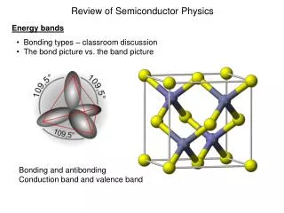
Semiconductor Device Physics
Semiconductor Device Physics. Lecture 5 Dr. Gaurav Trivedi , EEE Department, IIT Guwahati. Example: Energy-Band Diagram. For Silicon at 300 K, where is E F if n = 10 17 cm –3 ?. Silicon at 300 K, n i = 10 10 cm –3.


Semiconductor Device Physics
E N D
Presentation Transcript
Semiconductor Device Physics Lecture 5 Dr. GauravTrivedi, EEE Department, IIT Guwahati
Example: Energy-Band Diagram • For Silicon at 300 K, where is EF if n = 1017 cm–3 ? • Silicon at 300 K, ni= 1010 cm–3
Consider a Si sample at 300 K doped with 1016/cm3 Boron. What is its resistivity? • NA = 1016/cm3 , ND = 0 • (NA >> NDp-type) • p 1016/cm3, n 104/cm3
Consider a Si sample doped with 1017cm–3 As.How will its resistivity change when the temperature is increased from T = 300 K to T = 400 K? • The temperature dependent factor in (and therefore ) is n. • From the mobility vs. temperature curve for 1017cm–3, we find that n decreases from 770 at 300 K to 400 at 400 K. • As a result, increases by a factor of: 770/400 =1.93
1.a. (4.2) • Calculate the equilibrium hole concentration in silicon at T = 400 K if the Fermi energy level is 0.27 eV above the valence band energy. • 1.b. (E4.3) • Find the intrinsic carrier concentration in silicon at:(i) T = 200 K and (ii) T = 400 K. • 1.c. (4.13) • Silicon at T = 300 K contains an acceptor impurity concentration of NA = 1016 cm–3. Determine the concentration of donor impurity atoms that must be added so that the silicon is n-type and the Fermi energy level is 0.20 eV below the conduction band edge.
What is the hole diffusion coefficient in a sample of silicon at 300 K with p = 410 cm2 / V.s ? • Remark:kT/q= 25.86 mVat room temperature
Consider a sample of Si doped with 1016 cm–3 Boron, with recombination lifetime 1 μs. It is exposed continuously to light, such that electron-hole pairs are generated throughout the sample at the rate of 1020 per cm3 per second, i.e. the generation rate GL = 1020/cm3/s • a) What are p0 and n0? • b) What are Δn and Δp? • Hint: In steady-state, generation rate equals recombination rate
Consider a sample of Si at 300 K doped with 1016 cm–3 Boron, with recombination lifetime 1 μs. It is exposed continuously to light, such that electron-hole pairs are generated throughout the sample at the rate of 1020 per cm3 per second, i.e. the generation rate GL = 1020/cm3/s. • c) What are p and n? • d) What are np product? • Note: The np product can be very different from ni2 in case of perturbed/agitated semiconductor
Photoconductor Photoconductor • Photoconductivity is an optical and electrical phenomenon in which a material becomes more electrically conductive due to the absorption of electro-magnetic radiation such as visible light, ultraviolet light, infrared light, or gamma radiation. • When light is absorbed by a material like semiconductor, the number of free electrons and holes changes and raises the electrical conductivity of the semiconductor. • To cause excitation, the light that strikes the semiconductor must have enough energy to raise electrons across the band gap.
Net Recombination Rate (General Case) Chapter 3 • For arbitrary injection levels and both carrier types in a non-degenerate semiconductor, the net rate of carrier recombination is: Net Recombination Rate (General Case) Net Recombination Rate (General Case) where • ET : energy level of R–G center
Area A, volume A.dx JN(x) JN(x+dx) dx Continuity Equation Flow of current Flow of electron
Continuity Equation • Taylor’s Series Expansion • The Continuity Equations
Minority Carrier Diffusion Equation • The minority carrier diffusion equations are derived from the general continuity equations, and are applicable only for minority carriers. • Simplifying assumptions: • The electric field is small, such that: • For p-type material • For n-type material • Equilibrium minority carrier concentration n0 and p0 are independent of x (uniform doping). • Low-level injection conditions prevail.
Minority Carrier Diffusion Equation • Starting with the continuity equation for electrons: • Therefore • Similarly
Carrier Concentration Notation • The subscript “n” or “p” is now used to explicitly denote n-type or p-type material. • pn is the hole concentration in n-type material • np is the electron concentration in p-type material • Thus, the minority carrier diffusion equations are:
Simplifications (Special Cases) • Steady state: • No diffusion current: • No thermal R–G: • No other processes:
Minority Carrier Diffusion Length • Consider the special case: • Constant minority-carrier (hole) injection at x = 0 • Steady state, no light absorption for x > 0 • The hole diffusion length LP is defined to be: Similarly,
Minority Carrier Diffusion Length • The general solution to the equation is: • A and B are constants determined by boundary conditions: • Therefore, the solution is: • Physically, LP and LN represent the average distance that a minority carrier can diffuse before it recombines with majority a carrier.
Quasi-Fermi Levels • Whenever Δn =Δp ≠0then np ≠ ni2 and we are at non-equilibrium conditions. • In this situation, now we would like to preserve and use the relations: • On the other hand, both equations imply np = ni2, which does not apply anymore. • The solution is to introduce to quasi-Fermi levels FN and FP such that: • The quasi-Fermi levels is useful to describe the carrier concentrations under non-equilibrium conditions
Example: Minority Carrier Diffusion Length • Given ND=1016 cm–3, τp = 10–6 s. Calculate LP. • From the plot,
Example: Quasi-Fermi Levels • Consider a Si sample at 300 K with ND = 1017 cm–3 and Δn = Δp = 1014 cm–3. • The sample is an n-type • a) What are p and n? • b) What is the np product?
Example: Quasi-Fermi Levels • Consider a Si sample at 300 K with ND = 1017 cm–3 and Δn = Δp = 1014 cm–3. 0.417 eV Ec FN • c) Find FN and FP? Ei FP Ev 0.238 eV