Download
1 / 34
340 likes | 908 Vues
Marko Mikuž University of Ljubljana & J. Stefan Institute. Basic Principles of Detection of Ionizing Radiation. Radiation Physics for Nuclear Medicine First MADEIRA Training Course. Milano, November 18-21, 2008. Outline. Radiation in medical imaging Interaction of photons with matter

E N D
Marko Mikuž University of Ljubljana & J. Stefan Institute Basic Principles of Detection of Ionizing Radiation Radiation Physics for Nuclear Medicine First MADEIRA Training Course Milano, November 18-21, 2008
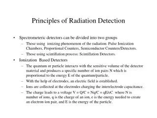
Outline • Radiation in medical imaging • Interaction of photons with matter • Photoelectric effect • Compton scattering • Statistics primer • Generic detector properties • A (non)-typical example • Scatter detector of Compton camera Main reference: G.F. Knoll: Radiation Detection and Measurement, J.Wiley&Sons 2000 Radiation Detection
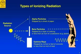
Radiation in Medical Imaging • Diagnostic imaging • X-rays • Planar X-ray • Transmission Computed Tomography (CT) • Contrast provided by absorption in body: μ ( r ) • Gamma sources • Emission Computed Tomography • SPECT • PET • Contrast provided by source distribution in body: A ( r ) • Both photons of Eγ ~ 20500 keV CT CT CT/PET Radiation Detection
X and γ-rays • X-ray tube • Spectrum of W anode at 90 kV • Typical radio-isotopes • Bonded to a bio-molecule • Radio-tracer Radiation Detection
Interaction of photons with matter • Photons unlike charged particles with continuous ionization exhibit “one-off” interactions • Primary photon lost in this process • Resulting charged particles ionize and can be detected • Photon flux is attenuated μ – linear attenuation coefficient [cm-1] λ = 1/μ – attenuation length, mean free path • Attenuation scales with density μ/ρ – mass attenuation coefficient [cm2/g] ρx – surface density, mass thickness [g/cm2] Radiation Detection
Mass attenuation coefficients • Linked to cross section by • For interesting photon energies two physical processes prevail • Photoelectric effect • Compton scattering • High vs. low Z comparison • σ higher by up to 3 orders of magnitude at low Eγ for high-Z • Features in spectrum for high-Z Complete set of tables for μ available at: http://physics.nist.gov/PhysRefData/XrayMassCoef/cover.html Region of interest Low Z High Z Radiation Detection
Photoelectric effect • Photon hits bound electron in atom • Electrontakes Eγ reduced by its binding energy • Momentum taken up by atom • Characteristic X-rays emitted • Tightly bound (K-shell) electrons preferred • Cross section rises by orders of magnitude upon crossing threshold – K-edge • Above K-edge 53I Radiation Detection
Compton scattering • Photon elastic scattering on (quasi)-free electron • Photon scattered and reduced energy Eγi Ee • Θ – photon scattering angle • µ = Eγi / mec2 • ε = Ee/ Eγi Radiation Detection
Compton scattering (cont.) • Electron energy spectrum • Maximum Eγ transfer at Compton edge – backward scattering • Small transfers for low Eγ • Photons continue with ~same energy change direction • Bad for photon detection ! • Even worse for imaging … • Photoelectric vs. Compton Eγ ~ 1 MeV • Use high Z for detectors • Use lower Eγ for imaging Radiation Detection
Statistics primer • N independent measurements of same quantity: • Frequency distribution function (discrete x) • Standard deviation from true mean • Experimental mean and sample variance Radiation Detection
Questions asked • How accurate is the measurement ? • Best experimental estimate • For u derived of non-correlated measurements of x,y,z,… • Is the equipment working properly ? • Confront measurements to (correct) model • Is the underlying model correct ? • Confront model to (proper) measurements Radiation Detection
Statistical model - Binomial • Photon emission and detection a random (stochastic) process, like tossing a coin: N trials, x successes • Counting experiment, integer (discrete) outcome • p - success probability, e.g. p = 0.5 for a (fair) coin • x – statistical variable, P(x) given by distribution: • Binomial • Valid in general, but awkward to work with Radiation Detection
Statistical model - Poisson • Often individual success probabilities p are small with a large number of trials N • Binomial (N, p) → Poisson (Np) • Possible to estimate both the mean and error from a single counting measurement ! Radiation Detection
Statistical model - Gaussian • If mean value of Poisson distribution ≥ 20 • Poisson → Gaussian • Combination of measurements, due to Central Limit Theorem, leads to Gaussian distribution • Two parameters (mean, width) • x can be a continuous variable Radiation Detection
Statistical tests • Confront measurement F(x) to model P(x) • Ignorant’s attitude: Compare by eye ? • Scientific approach: Conduct a statistical test ! • Most used: χ2test • Test yields probability P experiment matches model • If probability too low (e.g. P < 0.05) • Question measurement if believe in model ? • Question model if believe in experiment ? • Accept lower probability ? • Take different model ? • Repeat measurement ? • Conduct other tests ? … • Compare by eye ?? • Eternal frustration of statistics • False positives vs. False negatives Radiation Detection
Generic radiation detector • For any γ-ray detection the following sequence applies • γ interacts in detector material resulting in an energetic electron (and eventual additional photons) • Electron ionizes detector material, creating additional electron-ion (or electron-hole) pairs – very fast process • Applied electric field in detector separates charges which drift towards collecting electrodes • Alternative: charges recombine at specific centers producing (visible) light- scintillation • Moving charges induce current on electrodes according to Shockley-Ramo theorem – collection time from ns to ms d x • Sometimes E is strong enough to provoke further ionization – charge multiplication • Current signal gets processed and analyzed in front-end and read-out electronics Radiation Detection
What do we want to measure ? • Signal from detector - time-dependant current pulse • No charge trapping and no amplification collected charge Q = ∫i(t)dt = Qionization Ee • Ee ~ Eγin photopeak • Handle on Compton scattering ! • Q build-up during charge collection time • tcoll ~ d2/(μV) can be some ns for thin semiconductor detectors • Fast timing – narrow coincidences – reject random background in PET ! • Good reasons to count individual pulses, extracting Q and t • Still for dosimetry applications average current measurement can be sufficient (dose-rate) Radiation Detection
Signal (pulse) processing • Basic elements of a pulse-processing chain • Expanded view of preamplifier and shaper Radiation Detection
Preamplifier • Possible simple configuration • R – amplifier input resistance • C – sum of Cdet, Ccable and Camp • RC << tcoll: current sensitive • RC >> tcoll: charge sensitive • trise~ tcoll • tfall ~ RC • Vmax ~ Q/C • C is dominated by Cdet, which can exhibit variations • Useful configuration – feedback integrator • A x Cf>>Cdet: V independent of Cdet • Rfneeded for restoration to base-line, preventing pile-up Radiation Detection
Energy resolution • Intrinsic resolution • Statistical noise in charge generation by radiation • Expect a stochastic process with variance • Lower average ionization energy(e.g. Si or Ge) gives better resolution • Process not truly stochastic; all E lost must sum up to Eγ ! Corrected by Fano factor F • F depends on E sharing between competing processes (ionization, phonons) • Measured F ~ 0.1 in Si & Ge; resolution improved by factor 3 ! • Full-Width at Half Maximum → universally accepted FOM for resolution • For Gaussian distribution • So the energy resolutionR is Radiation Detection
Noise considerations • Intrinsic resolution deteriorates with additional noise sources in read-out • The signal and its noise; two sources • Fluctuations in velocity – thermal noise • Fluctuation in charge • Intrinsic fluctuations • Fluctuations in underlying leakage current if injected (or generated) discretely – Shot noise • Noise characterized by noise power spectrum - dP/dν • Thermal and Shot noise have white spectra: dP/dν = K • The signal gets conditioned by the preamplifier • For charge sensitive pre-amp • Thermal noise → equivalent voltage noise source • Shot noise → equivalent current noise source • Pre-amp (and other parts of the system) add their own noise sources • Sources (mostly) uncorrelated → noise contributions add in quadrature Radiation Detection
Shaper • White spectra – noise at all frequencies • Signal – frequencies around 1/tcoll only • Filter out low and high frequencies to improve S/N • Task of the shaper • Also shape signal so amplitude and time can be determined • Basic functionality: CR and RC filters Radiation Detection
τn= τ/n Shaper (cont.) • Several CR and RC filters in sequence, decoupled by op-amps: CR-RC, CR-RCn, … • Response of CR-RCn to step function V0 • For equal peaking time • CR-RC fastest rise-time – best for timing • CR-RCn with n > 4 symmetric – faster return to baseline – high rates Radiation Detection
Noise of detection system • Shaper with peaking time τreduces bandwidth • Noise of detector & read-out turned into equivalent charge fluctuations at input – equivalent noise charge ENC • FOM is signal to noise S/N = Q/ENC • For charge sensitive pre-amp • Thermal (voltage) noise • Shot (current) noise • No universal recipe • Optimizeτ case-by-case Radiation Detection
Dead time • Detection system can be inactive for dead-time τ for various reasons • Detector bias recharge (GM) • ADC conversion time • Two models of interference • Signals during dead-time pass by unnoticed • Non-paralyzable model • Signals during dead-time lost & induce own dead-time • Paralyzable model • Relation between observed pulse rate m and true rate n • Non-paralyzable model • Paralyzable model • Solve for n iteratively • Two ambiguous solutions Radiation Detection
Anger Camera – Mechanical Collimation • SPECT imager – Anger camera • Need collimator to reconstruct photon direction Typical collimator properties Anger 1957 Siemens 2000 Low efficiency, coupled to resolution (ε.σ2 ~ const.), worse @ higher Eγ, bulky standard medical imaging technique Radiation Detection
Compton Camera – Electronic Collimation • Replace mechanical collimator by active target (scatter detector) to Compton scatter the photon • Detect scattered photon in position sensitive scintillator (Anger camera head w/o collimator) • Reconstruct emitted photon from Compton kinematics • Old idea • Todd, Nightingale, Evrett: • A Proposed γ-Camera, Nature 1974 • Compton telescopes standard • instrument in γ-ray astronomy Radiation Detection
Compton Camera – The Principle • Measure position of scattering and absorption • Measure electron (and photon) energy • Each measurement defines a cone with angle Θ in space • Many cones provide a 3-D image of the source distribution Radiation Detection
Compton Camera – The Small Print • Error on the source position results from • Position resolution • Error on cone axis • Place absorber far from scatter (solid angle, cost) • Place scatter close to source –near field imaging • Electron energy resolution • Error on cone angle • Doppler broadening • Electron bound in atoms • , broadening in θ Radiation Detection
Rationale of Si as Scatter Detector • Silicon exhibits • Highest Compton/total x-section ratio • Smallest Doppler broadening • Excellent energy and position resolution • Mature technology • Simple operation (hospital !) • Reasonable cost • Low efficiency ~ 0.2/cm • Thick detectors 0.3 → ~1 mm • Stack for higher efficiency Radiation Detection
Energy Resolution • Statistical • ΔEFWHM = 2.35 √ F N • 140/511 keV: ΔEFWHM~ 55/200 e ~ 200/720 eV • Electronics • Voltage noise (Cint+Cdet) /√τp • Current noise √ (Idet τp) Even in optimized systems electronics noise dominates 1 keV FWHM (σnoise = 120 e) a challenge Radiation Detection
Silicon Sensors • 1 mm thick p+-n pad sensors • Pad dimensions 1.4 mm x 1.4 mm • Routed to bond pads at detector edge through double metal • Full depletion ~ 150 V for 1 mm • Very low leakage current ~ 50 pA/pad • Produced by SINTEF, Norway • 512-pad (16x32) detectors used for this prototype • Active area 22.4 mm x 44.8 mm Radiation Detection
VATAGP3 Read-Out Chip • 128-channel self-triggering ASIC produced by IDE AS, Norway • Charge-sensitive pre-amplifier • TA channel: fast-shaper (150 ns) & discriminator for self-triggering • Trim-DAC’s for threshold alignment • VA channel: low-noise slow shaper (0.5-5 µs) for energy measurement • Read-out of up to 16 daisy-chained chips • Serial: all channels • Sparse: channel triggering with address • Sparse ± specified number of neighbouring channels • 2 multiplexed analogue outputs (up, down) • Calibration circuitry for diagnostics 50 % - gain S-curve width - noise Radiation Detection
Silicon Pad Module Tc-99m (140.5 keV) • Si detector with four VATAGP3 mounted on 4-layer PCB hybrid • Measured noise figure 170 e0, corresponding to ΔE of 1.4 keV • VAshaping time of 3 µs used, but noise still dominated by voltage noise • Noise correlated to capacitance of double-layer routing lines on silicon Radiation Detection