Download
1 / 53
620 likes | 1.41k Vues
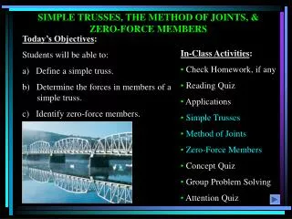
Today’s Objectives : Students will be able to: a) Define a simple truss. b) Determine the forces in members of a simple truss. c) Identify zero-force members. SIMPLE TRUSSES, THE METHOD OF JOINTS, & ZERO-FORCE MEMBERS. In-Class Activities : Check Homework, if any Reading Quiz

E N D
Today’s Objectives: Students will be able to: a) Define a simple truss. b) Determine the forces in members of a simple truss. c) Identify zero-force members. SIMPLE TRUSSES, THE METHOD OF JOINTS, & ZERO-FORCE MEMBERS • In-Class Activities: • Check Homework, if any • Reading Quiz • Applications • Simple Trusses • Method of Joints • Zero-Force Members • Concept Quiz • Group Problem Solving • Attention Quiz
READING QUIZ • 1. One of the assumptions used when analyzing a simple truss is that the members are joined together by __________. • A) Welding B) Bolting C) Riveting • D) Smooth pins E) Super glue 2. When using the method of joints, typically _________ equations of equilibrium are applied at every joint. A) Two B) Three C) Four D) Six
Trusses are commonly used to support roofs. A more challenging question is that for a given load, how can we design the trusses’ geometry to minimize cost? APPLICATIONS For a given truss geometry and load, how can you determine the forces in the truss members and thus be able to select their sizes?
Trusses are also used in a variety of structures like cranes and the frames of aircraft or space stations. How can you design a light weight structure that will meet load, safety, cost specifications, be easy to manufacture, and allow easy inspectioin over its lifetime? APPLICATIONS (continued)
A truss is a structure composed of slender members joined together at their end points. A simple truss is a planar truss which begins with a a triangular element and can be expanded by adding two members and a joint. For these trusses, the number of members (M) and the number of joints (J) are related by the equationM = 2 J – 3. SIMPLE TRUSSES (Section 6.1) If a truss, along with the imposed load, lies in a single plane (as shown at the top right), then it is called a planar truss.
With these two assumptions, the members act as two-force members. They are loaded in either tension or compression. Often compressive members are made thicker to prevent buckling. ANALYSIS & DESIGN ASSUMPTIONS When designing both the member and the joints of a truss, first it is necessary to determine the forces in each truss member. This is called the forceanalysis of a truss. When doing this, two assumptions are made: 1. All loads are applied at the joints. The weight of the truss members is often neglected as the weight is usually small as compared to the forces supported by the members. 2. The members are joined together by smooth pins. This assumption is satisfied in most practical cases where the joints are formed by bolting the ends together.
THE METHOD OF JOINTS (Section 6.2) A free body diagram of Joint B When using the method of joints to solve for the forces in truss members, the equilibrium of a joint (pin) is considered. All forces acting at the joint are shown in a FBD. This includes all external forces (including support reactions) as well as the forces acting in the members. Equations of equilibrium ( FX= 0 and FY = 0) are used to solve for the unknown forces acting at the joints.
STEPS FOR ANALYSIS • If the truss’s support reactions are not given, draw a FBD of the entire truss and determine the support reactions (typically using scalar equations of equilibrium). 2. Draw the free-body diagram of a joint with one or two unknowns. Assume that all unknown member forces act in tension (pulling the pin) unless you can determine by inspection that the forces are compression loads. 3. Apply the scalar equations of equilibrium, FX = 0 and FY = 0, to determine the unknown(s). If the answer is positive, then the assumed direction (tension) is correct, otherwise it is in the opposite direction (compression). 4. Repeat steps 2 and 3 at each joint in succession until all the required forces are determined.
If a joint has only two non-collinear members and there is no external load or support reaction at that joint, then those two members are zero-force members. In this example members DE, DC, AF, and AB are zero force members. Zero-force members can be removed (as shown in the figure) when analyzing the truss. ZERO-FORCE MEMBERS (Section 6.3) You can easily prove these results by applying the equations of equilibrium to joints D and A.
ZERO – FORCE MEMBERS (continued) If three members form a truss joint for which two of the members are collinear and there is no external load or reaction at that joint, then the third non-collinear member is a zero force member. Again, this can easily be proven. One can also remove the zero-force member, as shown, on the left, for analyzing the truss further. Please note that zero-force members are used to increase stability and rigidity of the truss, and to provide support for various different loading conditions.
Given: Loads as shown on the truss Find: The forces in each member of the truss. Plan: EXAMPLE • Check if there are any zero-force members. • First analyze pin D and then pin A • Note that member BD is zero-force member. FBD = 0 • Why, for this problem, do you not have to find the external reactions before solving the problem?
EXAMPLE (continued) + FX = – 450 + FCD cos 45° –FAD cos 45° = 0 + FY = – FCD sin 45° –FAD sin 45° = 0 FCD = 318 lb (Tension) or (T) and FAD = – 318 lb (Compression) or (C) D 450 lb 45 º 45 º FCD FAD FBD of pin D
Analyzing pin A: EXAMPLE (continued) FAD 45 º A FAB AY FBD of pin A + FX = FAB+(– 318) cos 45° = 0; FAB = 225 lb (T) Could you have analyzed Joint C instead of A?
P A H B C W CONCEPT QUIZ 1. Truss ABC is changed by decreasing its height from H to 0.9 H. Width W and load P are kept the same. Which one of the following statements is true for the revised truss as compared to the original truss? A) Force in all its members have decreased. B) Force in all its members have increased. C) Force in all its members have remained the same. D) None of the above.
CONCEPT QUIZ (continued) F F F • 2. For this truss, determine the number of zero-force members. • A) 0 B) 1 C) 2 • D) 3 E) 4
Given: Loads as shown on the truss Find: Determine the force in all the truss members (do not forget to mention whether they are in T or C). Plan: GROUP PROBLEM SOLVING • a) Check if there are any zero-force members. • Draw FBDs of pins D and E, and then apply EE at those pins to solve for the unknowns. • Note that Member CE is zero-force member so FEC = 0. If you didn’t see this simplification, could you still solve the problem?
FBD of pin D From geometry, tan-1(1/2)=26.57 GROUP PROBLEM SOLVING (continued) Y 600N D X 26.57 FCD FDE Analyzing pin D:→ + FX = 600 – FCD sin 26.57= 0 FCD = 1341 N = 1.34 kN (C) (Note that FCD = FBC!) • + FY = 1341 cos 26.57 –FDE = 0 FDE = 1200 N = 1.2 kN (T)
GROUP PROBLEM SOLVING (continued) FBD of pin E Y FDE 900 N E X 45 FEB FEA Analyzing pin E: → + FX = 900 – FEB sin 45= 0 FEB = 1273 N = 1.27 kN (C) • + FY = 1200 + 1273 cos 45 –FEA = 0 FEA = 2100 N = 2.1 kN (T)
FBC B FBD BY ATTENTION QUIZ • 1. Using this FBD, you find that FBC = – 500 N. Member BC must be in __________. • Tension • Compression • C) Cannot be determined • 2. For the same magnitude of force to be carried, truss members in compression are generally made _______ as compared to members in tension. • A) Thicker • B) Thinner • C) The same size
End of the Lecture Let Learning Continue
Today’s Objectives: • Students will be able to determine: • Forces in truss members using the method of sections. THE METHOD OF SECTIONS • In-Class Activities: • Check Homework, if any • Reading Quiz • Applications • Method of Sections • Concept Quiz • Group Problem Solving • Attention Quiz
READING QUIZ 1. In the method of sections, generally a “cut” passes through no more than _____ members in which the forces are unknown. A) 1 B) 2 C) 3 D) 4 2. If a simple truss member carries a tensile force of T along its length, then the internal force in the member is ______ . A) Tensile with magnitude of T/2 B) Compressive with magnitude of T/2 C) Compressive with magnitude of T D) Tensile with magnitude of T
APPLICATIONS Long trusses are often used to construct large cranes and large electrical transmission towers. The method of joints requires that many joints be analyzed before we can determine the forces in the middle part of a large truss. So we need another method to determine such forces.
In the method of sections, a truss is divided into two parts by taking an imaginary “cut” (shown here as a-a) through the truss. Since truss members are subjected to only tensile or compressive forces along their length, the internal forces at the cut members will also be either tensile or compressive with the same magnitude. This result is based on the equilibrium principleandNewton’s third law. THE METHOD OF SECTIONS
STEPS FOR ANALYSIS 1. Decide how you need to “cut” the truss. This is based on: a) where you need to determine forces, and, b) where the total number of unknowns does not exceed three (in general). 2. Decide which side of the cut truss will be easier to work with (minimize the number of reactions you have to find). 3. If required, determine any necessary support reactions by drawing the FBD of the entire truss and applying the E-of-E.
STEPS FOR ANALYSIS (continued) 4. Draw the FBD of the selected part of the cut truss. We need to indicate the unknown forces at the cut members. Initially we may assume all the members are in tension, as we did when using the method of joints. Upon solving, if the answer is positive, the member is in tension as per our assumption. If the answer is negative, the member must be in compression. (Please note that you can also assume forces to be either tension or compression by inspection as was done in the figures above.)
STEPS FOR ANALYSIS (continued) 5. Apply the scalar equations of equilibrium (E-of-E) to the selected cut section of the truss to solve for the unknown member forces. Please note, in most cases it is possible to write one equation to solve for one unknown directly. So look for it and take advantage of such a shortcut!
Given: Loads as shown on the truss. Find: The force in members KJ, KD, and CD. Plan: EXAMPLE a) Take a cut through the members KJ, KD, and CD. b) Work with the left part of the cut section. Why? c) Determine the support reactions at A. What are they? d) Apply the EofE to find the forces in KJ, KD, and CD.
Now take moments about point D. Why do this? + MD = – 45.6 (9) + 20 (6) + 30 (3) – FKJ (4) = 0 FKJ = − 50.1 kN or 50.1 kN ( C ) EXAMPLE (continued) Analyzing the entire truss for the reactions a A, we get FX = AX = 0. Then do a moment equation about G to find AY. ∑MG = AY (18) –20 (15) – 30 (12) – 40 (9) = 0; AY = 45.6 kN
EXAMPLE (continued) Now use the two force equations of equilibrium. ↑ + FY = 45.6 – 20 – 30 – (4/5) FKD = 0; FKD = − 5.5 kN , or 5.5 kN (C) → + FX = (– 50.1) + (3/5) ( –5.5 ) + FCD = 0; FCD = 53.4 kN (T)
1. Can you determine the force in member ED by making the cut at section a-a? Explain your answer. A) No, there are 4 unknowns. B) Yes, using MD = 0 . C) Yes, using ME = 0 . D) Yes, using MB = 0 . CONCEPT QUIZ
2. If you know FED, how will you determine FEB ? A) By taking section b-b and using ME = 0 B) By taking section b-b, and using FX = 0 and FY = 0 C) By taking section a-a and using MB = 0 D) By taking section a-a and using MD = 0 CONCEPT QUIZ
Given: The internal drag truss for the wing of a airplane is subjected to the forces shown. Find: The force in members IH, BH, and BC. Plan: GROUP PROBLEM SOLVING a) Take a cut through the members IH, BH, and BC. b) Analyze the right section (no support reactions!). c) Draw the FBD of the right section. d) Apply the equations of equilibrium (if possible try to do it so that every equation yields an answer to one unknown.
+ MH = – FBC (2) + 60 (2) + 40 (3.5) = 0; FBC = 130 lb (T) SOLUTION + ↑ FY = 80 + 60 + 40 – FBH sin 45º = 0; FBE = 255 lb (T) + → FX = FIH – 130– 255 cos 45º = 0; FIH = 310 lb (T)
1. As shown, a cut is made through members GH, BG and BC to determine the forces in them. Which section will you choose for analysis and why? A) Right, fewer calculations. B) Left, fewer calculations. C) Either right or left, same amount of work. D) None of the above, too many unknowns. ATTENTION QUIZ
2. When determining the force in member HG in the previous question, which one equation of equilibrium is best to use? A) MH = 0 B) MG = 0 C) MB = 0 D) MC = 0 ATTENTION QUIZ
End of the Lecture Let Learning Continue
Today’s Objectives: Students will be able to: a) Draw the free body diagram of a frame or machine and its members. b) Determine the forces acting at the joints and supports of a frame or machine. FRAMES AND MACHINES • In-Class Activities: • Check Homework, if any • Reading Quiz • Applications • Analysis of a Frame/Machine • Concept Quiz • Group Problem Solving • Attention Quiz
READING QUIZ • 1. Frames and machines are different as compared to trusses since they have ___________. • A) Only two-force members B) Only multiforce members • C) At least one multiforce member D) At least one two-force member • 2. Forces common to any two contacting members act with _______ on the other member. • A) Equal magnitudes but opposite sense • B) Equal magnitudes and the same sense • C) Different magnitudes but opposite sense • D) Different magnitudes but the same sense
Frames are commonly used to support various external loads. APPLICATIONS How is a frame different than a truss? To be able to design a frame, you need to determine the forces at the joints and supports.
“Machines,” like those above, are used in a variety of applications. How are they different from trusses and frames? APPLICATIONS (continued) How can you determine the loads at the joints and supports? These forces and moments are required when designing the machine members.
Frames and machines are two common types of structures that have at least one multi-force member. (Recall that trusses have nothing but two-force members). FRAMES AND MACHINES: DEFINITIONS Frame Machine Frames are generally stationary and support external loads. Machines contain moving parts and are designed to alter the effect of forces.
STEPS FOR ANALYZING A FRAME OR MACHINE 1. Draw a FBD of the frame or machine and its members, as necessary. Hints:a) Identify any two-force members, b) forces on contacting surfaces (usually between a pin and a member) are equal and opposite, and, c) for a joint with more than two members or an external force, it is advisable to draw a FBD of the pin. FAB 2. Develop a strategy to apply the equations of equilibrium to solve for the unknowns. Problems are going to be challenging since there are usually several unknowns. A lot of practice is needed to develop good strategies.
Given: The frame supports an external load and moment as shown. Find: The horizontal and vertical components of the pin reactions at C and the magnitude of reaction at B. Plan: EXAMPLE a) Draw FBDs of the frame member BC. Why pick this part of the frame? b) Apply the equations of equilibrium and solve for the unknowns at C and B.
+ MC = FAB sin45° (1) – FAB cos45° (3) + 800 N m + 400 (2) = 0 FAB = 1131 N EXAMPLE 800 N m 400 N CX CY 1 m 1 m 2 m FBD of member BC B 45° FAB Please note that member AB is a two-force member. Equations of Equilibrium:
Now use the x and y direction Equations of Equilibrium: • + FX = – CX+ 1131 sin 45° = 0 CX = 800 N • + FY = – CY+ 1131 cos 45° – 400 = 0 • CY = 400 N EXAMPLE 800 N m 400 N CX CY 1 m 1 m 2 m FBD of member BC B 45° FAB
1. The figures show a frame and its FBDs. If an additional couple moment is applied at C, then how will you change the FBD of member BC at B? A) No change, still just one force (FAB) at B.B) Will have two forces, BX and BY, at B.C) Will have two forces and a moment at B.D) Will add one moment at B. CONCEPT QUIZ
CONCEPT QUIZ (continued) D 2. The figures show a frame and its FBDs. If an additional force is applied at D, then how will you change the FBD of member BC at B? A) No change, still just one force (FAB) at B.B) Will have two forces, BX and BY, at B.C) Will have two forces and a moment at B.D) Will add one moment at B.
Given: A frame supports a 50-kg cylinder. Find: The reactions that the pins exert on the frame at A and D. Plan: GROUP PROBLEM SOLVING a) Draw a FBD of member ABC and another one for CD. b) Apply the equations of equilibrium to each FBD to solve for the six unknowns. Think about a strategy to easily solve for the unknowns.
+ MA = CY (1.6) – 50 (9.81) (0.7) – 50 (9.81) (1.7) = 0 ; CY = 735.8 N Applying E-of-E to member ABC: GROUP PROBLEM SOLVING (continued) FBDs of members ABC and CD CY CX 50(9.81) N 0.7 m 1.2 m 1.6 m DX DY • + FY = AY– 735.8 – 50 (9.81) – 50 (9.81) = 0 ; AY = 245 N • + FX = CX– AX = 0 ; CX = AX