Download
1 / 63
650 likes | 894 Vues
Solar Dynamics Observatory (SDO) Spacecraft Design and Operations Overview Mission PDR. David Ward. Agenda. Spacecraft requirements overview/driving requirements status Spacecraft trades and major changes since SCR Overview of architecture and spacecraft subsystems

E N D
Solar Dynamics Observatory (SDO) Spacecraft Design and Operations OverviewMission PDR David Ward
Agenda • Spacecraft requirements overview/driving requirements status • Spacecraft trades and major changes since SCR • Overview of architecture and spacecraft subsystems • Observatory operations concept • Technical resources • Mass, power, pointing, jitter, data capture, data completeness, propellant • Issues • Conclusion
Status of Spacecraft Requirements • Top-level spacecraft requirements (defined in MRD) have remained relatively stable since SRR/SCR. Among the changes, many stem from the replacement of SHARPP with AIA, as well as lessons learned from the SRR/SCR. • Removal of KCOR eased absolute pointing and particulate contamination requirements • Removal of the OFS from EVE eliminated local magnetic field requirements • Jitter requirements have been clarified through detailed discussions with the instrument teams • SHARPP data rates have been reallocated, allowing EVE to eliminate compression • Technical resource allocations were modified to share some project margin with subsystems • Since Autumn, more emphasis has been on Level 3 (and 4) requirements, further detailing subsystem requirement allocations and design decisions • Subsystem requirements began draft development in the Summer/Fall, and the project has been baselining documents after subsystem PDRs to allow for peer review of requirements • Subsystem requirements include verification matrices that follow the MRD style • Requirement, traceability, rationale, assignment and verification method are tracked for all requirements • At Level 4 (component specs/SOWs), documents are being created for standalone use, so that vendors do not have to search through multiple document to understand all of their requirements • Component level specs are reaching their final draft stages (one is baselined), and are nearly ready for this Spring’s procurement activities • At this point, spacecraft and subsystem requirements are in good shape to proceed into detailed design
Mission Design Drivers • The primary mission design drivers have remained constant through preliminary design: • High data volume, coupled with tight requirements on data loss and degradation • Drives requirement for high speed science data bus and Ka transmitter to downlink data • Also derives requirement for dedicated SDO ground station and high gain antenna control • Significant effort dedicated to Ka Transmitter breadboarding, data loss analysis and budgeting since SCR • Additional effort placed on HGAS calibration on-orbit, in order to improve RF gain, and thus bit error rate • Geosynchronous orbit • Drives launch vehicle and propulsion system requirements, and places SDO in high radiation environment and electrostatic return environment for contamination • Propulsion design has been modified to provide a backup GEO injection approach, and has converged on a more traditional GEO injection design • Detailed radiation analysis of preliminary parts list is underway, as well as design mitigation as necessary • Electrical systems will place a continued emphasis on grounding, on-orbit ESD, Common Mode Noise in recognition of special challenges of the orbit • Long mission life (5 year requirement, 10 year goal) • Drives reliability (especially of mechanisms), redundancy, & radiation requirements • Preliminary designs use mechanisms (gimbals, reaction wheels, filter wheels, etc) that have proven through life test and flight data their ability to meet the life requirements • Tight pointing, jitter, and coalignment requirements • Driving jitter requirements clarified since AIA brought on-board • Trade to add a Guide Telescope for each AIA Science Telescope minimizes “differential flexibility” risk and brings jitter approach in-line with proven TRACE approach • Preliminary analysis of jitter and pointing budgets shows requirements can be met using baselined design
Major Changes Since SCR • Replacement of SHARPP instrument suite with AIA instrument • At a concept design level, many of the spacecraft interfaces (power services, high speed bus, 1553) moved directly from SHARPP allocations to AIA; additional work ongoing to flesh out detailed interfaces (mechanical/thermal/electrical/data/pointing) • Minor redesign of the Instrument Module (IM) performed to give AIA telescopes more integration room; IM now more of a square than offset rectangle as was required by side-mounted SPECTRE • Decision to mount four Guide Telescopes directly to AIA Science Telescopes eases structural flexibility concern from separate mounting • Propulsion system trades revisited, resulting in change to more traditional MMH/MON-3 biprop design • GN&C team (ACS, Propulsion and Flight Dynamics) revisited original configuration that required thrusters on -X and either Y or Z axes, instead moving all thrusters to -X direction • Resulting configuration significantly eased contamination concern and allowed consideration of more traditional MMH/MON-3 system • In addition to programmatic benefits, higher Isp ACS thrusters gave a backup to the main engine • Separation of Solar Array and High Gain Antenna deployment functions • Deployables team traded several different actuators for these functions; baseline design uses QUIKNUT actuators for both the Solar Arrays and High Gain Antennae • Each array and HGA boom is on a separate deployment circuit; S/A’s autonomously deployed at separation, HGA’s deployed individually by ground command after Observatory is power-positive • Increased Solar Array size without affecting HGA coverage • Array area increased from 5.8 sq. meters to 7.7 sq. meters to account for reduced array output at lowest end of bus voltage range • HGA six month coverage protected without additional boom length by optimizing taper shape of arrays to account for distance between HGA and arrays • Solar arrays oversized compared to the load to minimize possibility of future array redesign and resulting impacts • Elimination of EVE’s OFS and EVE Electronics Box (EEB) move onto IM • Removal of OFS eliminated magnetic field sensitivity/requirements, leaving only dipole as a mag requirement • EEB is easily accommodated by larger IM (resized to accommodate AIA); move saves on intra-instrument harnessing, but places more difficult radiation burden on EEB
AIA 4 Ports 2 Active Primary Ka Comm 1 1 2 4 Primary Ka XMTR 3 2 4 5 3 6 HMI 4 Ports 2 Active 1 2 3 4 Redundant Ka Comm 1 4 Redundant Ka XMTR EVE 4 Ports 2 Active 1 2 2 5 3 3 4 6 Design Changes: SHARPP/AIA • Some minor spacecraft redesign resulted from replacement of SHARPP by AIA • Removal of side-mounted SPECTRE allowed for IM to be squared off, providing more room for AIA telescopes • AIA telescope overhang acceptable; does not interfere with HMI, EVE FOV’s (more difficult if either had KCOR’s wide stray light FOV) • AIA takes responsibility for controlling Guide Telescopes; pointing budgets very similar • AIA planning to use same Camera Electronics/CCD as SHARPP; thermal radiator requirements very similar • High Speed Bus for science data (shown below) is a simple interface replacement, and some reallocation of SHARPP data rate between AIA and EVE • With KCOR removal, particulate contamination requirements eased POST SCR Config. 8/03 Magritte SPECTRE KCOR AIA PDR Config. 12/03
Four pairs of canted thrusters surround the main engine, with each pair assigned to separate isolation banks The canting allows diagonal pairs to be used for X control, in addition to adjacent thrusters being used for Y and Z control Since the eight ACS thrusters are also biprop engines, they can be used to get to GEO in the event the main engine fails Thrust direction of all nine thrusters away from instruments, easing the contamination risk presented by propellant Design Changes: New Thruster Locations
Observatory Mechanical Configuration Composite Instrument module minimizes thermal distortion, places instrument radiators outboard and with clear thermal field of view HMI AIA EVE AIA (which uses GT signals for IMC) all on one face, HMI, EVE (which do not) on the other AIA EVE Spacecraft bus module provides Faraday cage and radiation shielding for s/c and instrument components HMI Two short tapered arrays, cell side out when stowed Internal propulsion module, allows for parallel integration and test flow early Redundant High Gain Antennae (HGA) at the end of rigid booms. Each antenna can be used continuously for ~ 6 months/year (scheduled antenna handovers twice/year)
SDO Propulsion Module Fuel Tank Pressurant Tanks Oxidizer Tank (Inside Cylinder And Frustum) Fuel/Oxidizer/ Pressurant Control Modules Thrusters (4 Places) Ka Transmitters and Switch (Panels Removed) Fill and Drain Valves Main Engine
Command & Data Handling Provides Spacecraft Processor for high-end Attitude Control algorithms, command/telemetry processing Up/Down card provides interface to S-band RF system Hardware command decoding for computer-free recovery Provides continuous 130 Mbps high-speed interface between Instruments and Ka-band RF system Communications Ka-band transmitter through two High Gain Antennae to downlink science data S-band Transponders connected to Omni antennae for receipt of ground commands (2 Kbps) and telemetry downlink (64 Kbps) via SDO Ground Station, USN, TDRS Supports orbit determination via turnaround ranging Power Two Solar Arrays for string-fault-tolerant power generation supporting a 1450 W load One Lithium Ion battery (100 A-hr) for launch and 72 minute eclipse survival at nominal load Power switching is distributed, with high current switches in PSE and low current distributed to various subsystems Software Complex algorithms computed on central processor, including ACS, Stored Commanding, Solid State Recorder, and Fault Detection & Correction ACS, C&DH, HGAS and Power each have smaller embedded processors for power switching, housekeeping telemetry generation, and subsystem-specific applications (Safehold, Load-shedding, Thermal Control) Common software used for RTOS, 1553 RT, Time, Memory Load/Dump, Power Switching, etc on all SDNs Attitude Control Jitter performance at focal plane to <0.5” (3σ), calibrated pointing accuracy of 10” (3σ) via zero-momentum, three-axis control with Reaction Wheels Star Tracker, Inertial Reference Unit, and Guide Telescope used for target/attitude determination Momentum unloading monthly with thrusters Propulsion MMH/MON-3 bipropellant design to raise orbit from GTO, perform E-W S/K, unload momentum 445N (100#) engine used for GTO (with 22N (5#) ACS thruster backup) All thrusters on aft end of Observatory to limit contamination, improve observatory modularity Mechanical & Mechanisms Designed for EELV (Delta IV 4040 or Atlas V 401) Octagon structure with electronics mounted to inside of exterior walls for better thermal heat rejection On-orbit symmetry to minimize momentum buildup Deployable solar arrays and high gain antennae with uninterrupted coverage on one antenna for 6 months/year (no handovers needed) HGA pointing to 0.25° to support Ka link margin Continuous antenna pointing on same HGA (slip rings) Thermal Combination of passive/active design Software controlled operational heaters (optical bench) Thermostatic control of survival heaters Hybrid approach or “toasty cavity” and individual line heaters to minimize risk in propulsion thermal design SDO Spacecraft Subsystem Overview
to Up/Down B RW #1 Synchronous Serial Bus RW #2 RW #3 RW #4 ST #1 RT ST #2 from Instruments Housekeeping SDN to Ka- Band Housekeeping SDN RT Gimbal Interface CDH B RT DC-DC Converter High Speed Data Ka Band to Up/Down A Pwr Switching DC/DC Converter Bulk Memory & DC/DC Converter BC Synchronous Serial Bus S/C Processor RT H/W decoded cmds Uplink/Downlink S Band SDN S XPNDR A DC-DC Converter 3 dB Hybrid Pwr Switching S XPNDR B to Omnis from S Comm A 28V power to SBC, Ka Comm, S XMTR SDO Electrical Architecture 28V Power to ACS sensors, actuators &heaters Ka XMTR A HMI HMI Optics & CEB High Speed Data Ka Band ACE A Ka XMTR B Power Switching RT DC/DC Converter Waveguide Switch CSS from Ka Comm B HMI Inst Electronics DC-DC Converter RT Bulk Memory & DC/DC Converter BC ACE SDN AIA S/C Processor RT to High Gain Antennae GT’s RT RWA I/O Uplink/Downlink S Band SDN to S- Band EVE H/W decoded cmds ESP AEB Prop Pyro board DC-DC Converter 4 Optics & CEB Thermistors, HGA sensors EVE IEM (incl. SDN) MEGS 28V power Engine Valve Driver boards Pwr Switching GCE CDH A RT IRU RT Pwr Switching DC-DC Converter RT 1553 Bus Propulsion RT Gimbal Interface RT RT Engine Valve Driver boards Prop Pyro board Solar Array Module Deploy Circuits 3 Output Modules PSE SDN Solar Array Module Battery Module PSE SDN DC-DC Converter 3 Output Modules DC-DC Converter RWA I/O CSS ACE SDN 28V Power to Gimbal drives, Instrument Module thermal control PSE RT DC-DC Converter Power Switching 28V power 28V power ACE B Solar Array Solar Array 28V Power to ACS sensors, actuators & heaters Battery
Subsystem Data Node Serves as the embedded processor for many of the spacecraft avionics boxes Uses a Motorola RH-CF5208 ColdFire processor for processing Provides MIL-STD-1553 for communications with the spacecraft processor and cPCI for backplane communications Provides external interface to command a processor and backplane reset without changing the status of the other circuitry Also provides passive and active analog conversion circuits Common SDN software includes RTEMS RTOS and GSFC-developed software bus Prototype unit completed in Fall 2003, allowing for ringout of HW/SW interfaces prior to subsystem breadboard deliveries Subsystem Power Node Since SCR, split into two boards to provide all of the common power requirements The Power Conversion Card (PCC) provides DC/DC converters for 2.5, 3.3, 5, and 15 V, and provides a staggered enabling for those voltages to deal with FPGA power-on issues The PCC contains voltage monitoring circuitry to provide a power-on reset signal to the other electronic cards in the event one of the regulated voltages exceeds limits The PCC provides an external interface to command a power-on reset for the S Comm Card and the PSE, which are unswitched The Low Power Switch Card (LPSC) provides 16 switched services (8 @ 1A, 8 @ 2A) for further distribution of 28V power In the event of a converter regulation anomaly, the switches are configured to hold state as long as the 28V power is still supplied (all LPSC’s are on switched 28V services) Common Design Elements
Additional Spacecraft Design Highlights • Preliminary design progression results in detailed allocation of requirements • Observatory-wide interfaces like power switches and 1553 bandwidth allocation have preliminary designs, which show adequate spare services for PDR • “Orphan functions”, such as heater/thermistor services, the waveguide RF switch driver, deployment pots and separation switches have all been assigned to avionics • Propulsion redesign added pyro valves, whose drivers have been assigned to the ACE (as were the thruster and isolation valve drivers) • Twelve of sixteen hardware decoded commands assigned; they include processor and full resets for the S Comm cards and the PSE sides, spacecraft processor resets and a command to switch either spacecraft processor from a non-BC mode (TBD, either RT or Standby) to BC • Longer development items such as the SDN core and components of the Ka Transmitter have breadboard/prototype designs to work out design details • Integrated Ka Modulator breadboard completed in the Fall, followed by Ka Solid State Power Amplifier breadboard completed this Winter and preparing for performance and life degradation testing • Reaction Wheel and Inertial Reference Unit interfaces simplified (eliminate 1553) • RWAs are required for Safehold, and IRU may be when detailed design is complete • Since 1553 will not be used as a Safehold data interface, decision was made to simplify the component designs by only using one data interface
Observatory Operations Concept • Allows Functional and Operations overview of system design as a part of the “Big Picture” of requirements, Implementation Approach, and Ops Concept rather than as isolated requirements • Mission operations are arranged into five time-sequenced phases, which include detailed modes or activities that are also described in the following charts • Launch and Acquisition Phase • In-orbit Checkout & Orbit Circularization Phase • Instrument Commissioning Phase • Science Mission Phase • Normal Mode • Periodic Calibrations/Housekeeping • Eclipse Mode • Stationkeeping & Momentum Management • Safehold & Emergency Modes • Disposal Phase • The activities listed under Science Mission Phase are described in the context of that phase, but the capabilities are not limited to only that phase • The safeguard capabilities described in Safehold and Emergency Modes exist in every phase • Momentum management will be performed in every phase, but the once per four week constraint does not apply to the first two phases • Eclipse mode preparations are similar for all phases; for the early phases some components not yet powered
Launch and Acquisition • Phase covering pre-launch configuration until Observatory is power-positive and pointing at the sun • Observatory kept in low-power configuration: Instruments (& decontamination heaters) off, redundant units off, “science data components” (Ka Comm, Ka XMTR and Star Trackers) off • Launch until separation is approximately 45 minutes to a separation altitude of 300km • Separation altitude increased to reduce high momentum buildup due to atmospheric drag (at 185km) • Transmitter powered minutes before separation to allow for telemetry at separation (now expected through existing ground network station at Overburg, South Africa, Perth or Dongara Australia) • TDRSS available as contingency/backup • Autonomous Solar Array deployment and Reaction Wheel power application at separation, based on separation signals backed by software sequencer • Attitude Control System acquires sun in 45 minutes from separation rates to within 15º of the sunline • Rate damping can begin immediately after separation, but CSS sun errors are ignored until array deployment is sensed • Following discussions with KSC, SDO LV IRD specifies [0.25,0.25,0.25]°/s, which will eliminate need for thruster-based momentum unloading until after Observatory is power-positive (capability for ground commanded unloading still exists in the event of a separation anomaly) • Once the observatory is power-positive: • Instrument CCD decontamination heaters powered on (Instruments remain off) • Power on GCE (includes Housekeeping card) to provide additional thermistor data • Deploy the HGAs nominally within 2 hours of separation
In-Orbit Checkout • Phase used during first weeks to checkout and calibrate Observatory • Phase is concurrent with orbit circularization phase • Spacecraft components brought on-line, and capabilities/modes checked • Hot backup ACE powered on • High Gains deployed within hours after separation • ACS/Propulsion Checkout and calibration • Safehold checkout • Sensor Checkout/Calibration – IRUs, Star Trackers • Inertial Hold / Slew Capability checkout prior to fist planned maneuver • Thruster checkout prior to first planned maneuver (phasing for 5lb thrusters) • Observatory communications via external ground networks and SDO ground station • SDO dedicated ground station not available for continuous coverage until 3rd apogee maneuver • Instruments not powered on until all large apogee maneuvers complete • Maintains power margin in the event of an anomaly • Instrument CCD decontamination heaters remain on • Instrument doors remain closed. • High rate science data system (Ka-Comm, Ka-XMTR, HGAs) brought online for HGA pointing calibration and system checkout once at GEO slot
Orbit Circularization • Phase used during first weeks to circularize the orbit from the GTO and place SDO in its geosynchronous slot at 102ºW. • Phase is concurrent with In Orbit Checkout phase • Four (4) large Apogee Motor Firing (AMF) and three (3) small Trim Motor Firing (TMF) maneuvers are planned to place SDO in its final geosynchronous slot • AMF maneuvers use 445N (100#) thruster, TMF maneuvers use 22N (5#) thrusters • Approximately 2 weeks to complete • Total maximum duration for any maneuver activity will be less than ~90 minutes • Maximum slew time of 20 minutes before/after, settling, 50 minute maximum Delta V • Observatory may be pointed to any orientation during maneuver, so power, thermal, other designs must take 90 minute off-pointing as a requirement • Maneuvers are not time critical • If a maneuver is aborted or missed it can be made up later with no penalty • Observatory communications via external ground networks and SDO ground station • Thruster burns must be started and completed within view of one (or more) ground station • Consideration given to slight delay of apogee burns until Observatory in sight of station • Commands for maneuvers uploaded to Absolute Time Sequence buffer, rather than singularly commanded from ground
Instrument Commissioning • Instrument calibration and commissioning begins once on-station and lasts 30 to 60 days • Instruments are powered on (if not already) and optics doors are opened • Observatory communications through SDO ground station for S and Ka band • High rate science system brought on line (Ka-Comm, Ka-XMTR, HGAs) • HGA calibration is performed to remove static misalignments • SDO Ground Station tracks RF power while HGA performs raster slews • Instruments begin producing science data • Science data distributed directly from SDO ground station to SOCs • Instrument operations support from both MOC and SOCs • Spacecraft supports instrument calibration roll maneuvers and off point maneuvers • Maneuvers similar to periodic instrument calibration maneuvers described later
Nominal Mission Mode (Science Phase) • Expected to be phase that mission stays in 99% of time once at GEO, with few operational activities/interruptions normally planned • Ka-band science data is downlinked through SDO ground station and distributed to SOCs on continuous basis • S-band housekeeping data is collected by ground site and distributed to MOC, which further distributes data to SOCs • Nominal downlink rate is 64 kbps to the SDO ground station (data on RF carrier) • Twice daily periods of s-band omni antenna RF interference may degrade H/K data • S-Band data rate may be reduced to improve link margin during interference times • Orbit tracking operations performed two consecutive days a week • 6 passes (30mins each) each day from the SDO ground station and 1 pass (30 mins) each day from an external ground station (Hawaii) – potential to reduce tracking to bi-weekly • RF reconfiguration required for tracking, data placed on subcarrier and data rate lowered • Instruments SOCs will have a normal window each weekday to command Instruments and uplink loads with all commands passing through MOC to ground site • Anticipate weekly loads since instruments are full sun viewing with routine operations • Contingency command periods if on-duty FOT member(s) are contacted and bring up command link • Spacecraft data recorder maintains circular buffer with 24 hours of housekeeping data in order to capture anomalies in case of data loss • Attitude control system autonomously points reference boresight to sun and maintains proper rotation about sunline • Proper orientation is achieved by Inertial slew to sunline using Star Tracker attitude, then switching to Guide Telescope for science pointing
Periodic Calibrations/Housekeeping There are several periodic interruptions to the nominal science mission mode: • Stationkeeping and Momentum Unload maneuvers, Instrument Calibration (Roll and Off-point) maneuvers, eclipses (earth and moon), HGA handovers • All scheduled interruptions which cause science data loss are included in the Data Capture Budget • Twice a year HGA Handovers • Each HGA has an unobstructed field of view for approximately six months • Need to turn on Ka-Transmitter a few hours before handover to stabilize TCXO • Periodic HGA calibration may be required to maintain HGA pointing requirement • Thermal effects (to HGA boom) may degrade HGA pointing • RF signal strength degrades rapidly as HGA boresight pointing drifts outside the nominal antenna beamwidth • Instrument teams have identified periodic calibration activities • Roll maneuvers to observe solar shape • Off-point maneuvers for flat fielding and optical distortion calibration • Alignment adjustments – to align instrument to reference • Most instrument calibrations are infrequent, but AIA Guide Telescope/Science Reference adjustments, coordinated with HMI Alignment Leg adjustments, planned for up to once every two weeks
Instrument Calibration Maneuver Details • HMI: • Off point twice a year: up to +/- 30 arcminutes (~ solar diameter) about twice a year: ~20 positions/5 minute dwell at each position. This is a scan and step pattern. • 360 degree roll twice/year: 16 positions/22.5 degree steps/15 minute dwell at each position. • Alignment adjusts anticipated up to every two weeks: adjust HMI mounting legs to keep instrument aligned with reference (Guide Telescope) and keep Image Stabilization System (ISS) in range • EVE: • Cruciform off-point scans quarterly: 180 arcmin mapped at 3arcmin per step with dwell at each position of 30 seconds (total of 60 dwell points) • FOV Maps quarterly: 25 point, 5x5 map, 5arcmin/step covering +/- 10 arcmin each axis, hold each position for 60 secs then advance • AIA: (preliminary, somewhat based on similar SHARPP conversations) • Roll & off point calibrations perhaps twice a year (match to HMI timeline) • GT calibration (frequency is TBD), scans of few arcminutes wide, one in pitch and one in the yaw direction. • ACS will use a Star Tracker for knowledge, so we can complete these maneuvers without the GT signals. • High-rate science data is needed during the dwell points in the calibration maneuvers • High-rate science data is not needed during the calibration slews, only during dwell periods: this applies to both off-points and rolls. • Must ensure HGA coverage while attitude changes for slews – requires coverage planning • Maneuver sequences require spacecraft and instrument coordination • FOT will direct activities and produce coordinated activity plans and time-tagged command loads • Maneuver sequences will be performed by on-board time-tagged command loads
Eclipse Observatory requirement in this phase is to survive and minimize impact on science operations • Some Observatory configuration changes are made at the start of eclipse • Instruments are left powered, and instrument and spacecraft (optical bench) thermal/heater power increases to minimize thermal distortions during eclipse • Attitude control reverts to Star Trackers, due to loss of Guide Telescope signal • Arrays sized to fully recharge battery before next eclipse • Prior to the start of eclipse season the battery charge control algorithm will be set to increase battery state-of-charge to 100% pre-eclipse • At the end of the season the battery will be returned to a reduced state-of-charge to prevent overcharge • Observatory Failure Detection and Correction will be configured for eclipse • Deeper than normal battery discharge • Safehold designed to respond properly without coarse sun error input • Ka-Band subsystem will continue to perform • Ka communications may be degraded due to thermal effects on antenna booms • Instruments will continue to produce science data and expect to receive it on a best effort basis • Recovery from eclipse state budgeted at 1 hour after eclipse exit (for HMI science data) • Recovery defined as achievement of pointing/alignment, thermal requirements after eclipse
Stationkeeping/Momentum Management • Required operations to keep SDO within its orbit “slot” at 102º W and to maintain Observatory angular momentum near zero • To meet data capture requirements, this phase is only budgeted to interrupt science once/month • Stationkeeping burns (Delta-V) alone require a twice yearly interruption • Momentum management (Delta-H) will occur approximately monthly (actually every 4 weeks) • Requirement on spacecraft to handle 5 weeks period between momentum unloads, which allocates 4 weeks for nominal operations and 1 week for Safehold operations • One hour allocated for science interruption due to stationkeeping and 30 minutes for momentum management • During Delta-H spacecraft remains sun pointing but pointing control is +/- 5º • During Delta-V spacecraft may be off pointed up to 45º from the sun-line for up to 30 minutes • Maximum offset of 15º from the XY plane to minimize sun on instrument CCD radiators • Major reconfiguration (instrument power, Ka RF) not necessarily warranted unless power constraints require non-essential power to be reduced • Since thrusters moved to bottom deck, instrument doors do not need to be closed during maneuvers (to avoid contamination effects) • Given nature of operation, the SDO (or alternate) ground site is maneuver critical. • All stationkeeping and momentum management burns qualify as “critical operations” that must be viewed by the ground. • Can roll the spacecraft or delay burn time to ensure good communications (null avoidance, improve omni antenna coverage) for SK (or momentum dump) maneuvers. • An alternate ground station may be substituted for the SDO site if the SDO ground site is unavailable • Instrument teams will receive a 1553 warning message prior to and upon completion of each maneuver • Instruments will take pre-described action upon receipt of critical event notification commands
Safehold/Emergency Modes • Several capabilities will exist on the Observatory for “safing” in the event of an anomaly • Fault Protection software (FDC/TSM/RTS) in main spacecraft processor to respond to anomalous housekeeping telemetry • For attitude control anomalies, Observatory will drop into a simpler sun-pointing control mode either controlled by spacecraft processor (Sun Acq) or by independent ACE SDN • Independent ACE safehold can be commanded by ground or by spacecraft processor as response to FDC actions • Loss of “I’m OK” communications between ACE and s/c processor will cause ACE to enter Safehold • Safehold works without ground intervention until momentum limits reached • Momentum capabilities sized for one week of control before ground commanded unload performed • Safehold will not autonomously fire thrusters to unload, avoiding possibility of tumbling spacecraft • Safehold and Sun Acq are sun pointing. Same orientation as nominal science pointing • Some consideration being given to a Safehold command to effect a coarse roll about sunline, in order to move out of communication “null” • For power anomalies, spacecraft processor and PSE have layered load-shedding algorithms to reach lowest power state • Spacecraft processor can power-off individual components switched by various LPSC’s (Star Trackers, Ka Comm, optical bench thermal control) • Independent PSE load-shedding powers off services at a lower state of charge/battery voltage (can only open switches at Output Module level, turning off instruments, possibly the GCE, Ka Transmitter, if not already powered off by spacecraft processor) • Critical event notification commands have been identified to inform instruments of current or pending conditions. • Commands sent from main processor across the 1553 bus • Commands indicate safehold entry, pending load shed power off, eclipse entry, etc • Loss of the time distribution message across the 1553 can be used to indicate loss of main processor or 1553 • Uplink communications path is redundant and receiver and uplink card are on unswitched power • Hardware commands decoded in the uplink card hardware allow critical subsystem reconfiguration to recover nominal on-board communications
Disposal • At end of mission, NASA policy requires disposal of SDO into an orbit that won’t interfere with other spacecraft • Increase altitude to >300 km above GEO orbit • The actual de-orbit altitude is GEO + 300 km + X, where X is a function of the spacecraft mass and cross-sectional area. • Operations similar to orbit circularization at beginning of life • In order to ensure enough power for operations, instruments and science-oriented spacecraft components will be powered off • PDR Orbit Debris Assessment has been completed by Josephine San, and is in SDO CM review
Technical Resources Management • At project level, the following technical resources are being managed: • Mass, power, alignment/pointing, propellant, data capture, science data bus data rate, bit error rate (to meet data completeness), 1553 bandwidth, RF link margins • Mass and Nominal Power allocations baselined prior to SCR, with allocation increases made in late October, along with baselining Eclipse Power • Original allocations matched SCR estimates, with process requiring CCRs for any increases in allocation as a way to slow resource growth • By October, resource growth had slowed considerably, allowing for project to allocate some of its reserve to each subsystem and instrument team to be held at their level (per a SCR recommendation) • Project still holds reserve for each configured budget to maximize likelihood of hitting “percentage targets” (25% margin at PDR, 15% margin at CDR) • Four additional power states will be baselined: Launch, Orbit Raising, Survival, Stationkeeping • As shown on the following charts, SDO’s technical resources show an appropriate level of margin for PDR design maturity • Mass and power well above 25% margin for all modes, and are measured against worst-case failure conditions (12% decreased the solar array capability in the normal mode case and 13% increased current draw in the eclipse case) • Pointing/alignment/jitter budgets are challenging, but achievable using available components/methods • Data capture/completeness well analyzed, and science/housekeeping bus bandwidths correctly allocated • Propellant still has margin with a worst-case stackup, and an option exists to build more margin if necessary • In the following charts, the terms “Project reserve” and “margin” are not interchangeable • Project reserve = total capacity - total allocations: the allocation margin held at the project level • Margin = total capacity - current best estimates: the actual measure of project resource margin • Values listed on the next page are “margin”
Technical Resources Status/Margins Detailed breakdowns of mass, power, 1553 budgets available in backup charts.
Mass Budget Details Mass budget shows comfortable margin Project reserve is healthy for additional allocations if necessary Budget based on 3200 kg separation mass. Margin measured against dry mass, given a known propellant load
Sunlit Power Budget Details Normal mode shows comfortable margin Project reserve is healthy for additional allocations if necessary Budget based current solar array size, with generation capacity limited by bus voltage, assuming one failed cell (worse failure than failed string or failed PWM.)
Eclipse Power Budget Details Eclipse mode shows comfortable margin Project reserve is healthy for additional allocations if necessary Budget based on 100 A-hr battery with one failed cell. Eclipse is 72 minutes long and allowed DoD is 60%.
SDO Pointing/Alignment Budgets • Pointing allocations very similar to those at SCR, as AIA has similar requirements to the SPECTRE and Magritte instruments. • Requirements baseline held off to better understand AIA requirements and performance, but rapidly converging on final allocations • For the areas of most concern (AIA absolute pointing, HMI in IMC FOV), there is adequate margin for performance surprises • Science reference absolute pointing (10”, 3σ) • Heritage requirement from KCOR, kept as an internal requirement to serve as foundation for meeting all other requirements below • High frequency: 5”; seasonal variation 3”; calibration errors 1”: Total error: 9” (3σ) • Most significant contributor is spacecraft jitter; thermal shift expected to be <1”, well within allocation • AIA absolute pointing (75”, 3σ) • High frequency: 5”; seasonal variation 4”; biases and other one-time effects 48.75”: Total error: 57.75” (3σ) • Most significant contributor are ground/launch shift effects • Sun in Guide Telescope Linear FOV (95”, 3σ) • Required to make sure all four AIA Guide Telescopes can be used simultaneously • Total error: 77.75” (3σ) • Worst-case assumption, based on AIA absolute pointing estimate summed with 20” SciTel/GT coalignment per AIA telescope • HMI in IMC field of view (14”, 3σ) • Requirement set so that HMI does not have to adjust alignment legs on a daily basis (every two weeks is the current baseline) • High frequency: 5”; seasonal variation 5.92”; leg adjustment errors 2.0”: Total error: 12.92” (3σ) • Current analysis shows thermal shift allocated at 5” is less than 1” after an eclipse, leaving unofficial CBE near 8”, well within requirements • HMI in adjustment range of legs (200”, 3σ) • High frequency: 5”; seasonal variation 5.92”; biases and other one-time effects 129.80”: Total error: 140.72” (3σ) • Comfortable margin available to staying within range of legs • EVE/ESP absolute pointing (450”, 3σ) • High frequency: 5”; seasonal variation 5.92”; biases and other one-time effects 304.15”: Total error: 315.07” (3σ) • Comfortable margin available to staying within EVE’s performance range • Jitter performance (monitored as project risk #58) described on next two charts • Conservative HGA pointing budget shows 0.25 met with on-orbit calibration
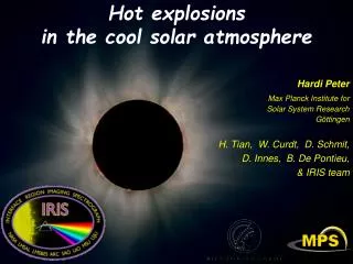
-2 10 -4 10 /Hz) 2 -6 10 CCD PSD(z) (asec -8 10 -10 10 -12 10 -2 -1 0 1 2 3 10 10 10 10 10 10 Frequency (Hz) Spacecraft Jitter • Detailed discussions with HMI & AIA teams developed the two formulae that define the SDO Jitter requirement. • HMI alone is concerned with misregistration, primarily concerned with disturbances between approximately 0.01 - 10 Hz (difficulty in combining filtergrams to create a Dopplergram) • HMI and AIA are both concerned with blurring, all disturbances above 0.01 Hz are included • Formulae below show the agreed method for calculating jitter at each focal plane • PSD represents the disturbance PSD caused by spacecraft and instrument disturbances • ATF is the attenuation transfer function of the HMI or AIA Image Stabilization System • The final terms are frequency weighing functions, which result in the frequency ranges discussed above Unattenuated PSD Attenuation Transfer Function Attenuated PSD Cumulative Summation
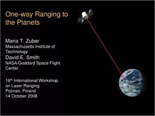
-2 10 -1 10 -4 10 /Hz) 2 -6 CCD Cumulative RMS (asec) -2 10 10 -2 10 CCD PSD(z) (asec -8 10 -4 -1 /Hz) 10 10 2 -3 10 -10 -6 10 10 CCD Cumulative RMS (asec) CCD PSD(z) (asec -2 -8 10 -12 10 10 -4 10 -10 -2 -1 0 1 2 3 -2 -1 0 1 2 3 10 10 10 10 10 10 10 10 10 10 10 10 10 Frequency (Hz) Frequency (Hz) -3 10 -12 10 -2 -1 0 1 2 10 10 10 10 10 -2 0 2 10 10 10 Frequency (Hz) Frequency (Hz) Spacecraft Jitter • Jitter requirements met with margin if careful attention placed on RWA/structure interaction • Analysis shows that of all disturbances considered, the major contributor is RWA imbalance resonating at a spacecraft flexible mode (HGA, GT NEA, torque quantization, slosh, instrument mechanisms also analyzed) • Results assume four wheels at same speed, with commercially available mass balancing • Results show that both ISS are adequate to effectively eliminate expected 0.01 - 10 Hz disturbances • Table below shows the impact of limiting wheel speeds below 1800 rpm (30 Hz), most significant modes (besides HGA/solar array modes near 2 Hz) are above 30 Hz • To establish additional jitter margin, ACS can operationally limit wheel speeds < 1800 rpm by ensuring that momentum buildup does not require a wide range of wheel speeds on-orbit (current estimate <1000 rpm) RWA resonance HGAS resonance AIA, unlimited wheel AIA, limited wheel
High Gain Antenna Pointing With on-orbit calibration, HGA pointing meets pointing requirement, even assuming conservative XTE/TRMM pointing assumptions
Science Data Capture/Completeness/Bandwidth • A simple way of expressing the HMI data capture needs is “capture 99.99% of the data, 95% of the time” • Data capture: 95% requirement, generally across longer time scales • includes outages over large time periods, due to eclipses, maneuvers, rain, etc., where multiple HMI observations are lost • Data completeness: 99.99% requirement generally over short time scales • includes dropouts (bit errors) over small time periods resulting in individual lost frames • Multiple lost frames cause a single HMI observation to be lost • Definition time scale is 10 minute observation period • Up to 300 frames can be lost (of 3,000,000) in 10 minutes and meet data completeness • When this number is exceeded, losses fall into data capture category • Data capture also covers maneuvers, eclipses, etc where all data is lost • SDO Data Capture is met with ample margin and detailed in SDO Data Capture Budget • The data capture requirement for HMI has recently been changed to 95% over a 72-day period. • Twenty two (22) 72-day periods over five years must meet the 95% data capture requirement to meet full mission success. • The 72-day periods will not be scheduled and nominally will run consecutively. If an data loss (or multiple losses) causes the 95% budget to be missed, a new 72-day period will be started • A 72-day period centered around eclipse season meets the 95% data capture criteria with very little margin • SDO Data Completeness is met by our RF link design and prevention of bit errors in instrument or spacecraft electronics • Science data frames are compressed therefore one uncorrectable bit error results in one lost frame • Frame error rate described by 99.99% can be converted to a bit error rate (BER) and allocations for BER distributed among subsystems in the science data path • BER for hardware components is achieved by evaluating semiconductor parts for radiation tolerance and Single Event Effects (SEEs) rates; BER for RF downlink is part of the link calculation and is calculated after forward error correction such as Reed-Solomon and Convolutional encoding. • Almost the full 130 Mbps science downlink capability is allocated to the instruments to avoid wasteful downlink of fill frames • Individual instrument allocations regulated by Ka Comm card TDM table which samples data from six separation 1355 ports • Replacement of SHARPP with AIA resulted in reallocation of data rate among instruments • AIA originally requested 58 Mbps, now allocated 67 Mbps • EVE originally requested 2 Mbps, now allocated 7 Mbps, eliminates compression altogether • HMI already using lossless compression, constant at 55 Mbps
On Board ElectronicsRF DownlinkCompleteness (Required) • RF Link • 5.0E-09 • Ground • 0.0 • = 99.991% (99.990%) • = 99.921% (99.900%) • = 99.638% (99.600%) • Instrument • HMI 1.0E-10 • AIA 5.0E-08 • EVE 2.25E-8 • Ka-Card • 1.0E-10 Data Capture/Completeness Breakouts
Propellant Budget Overview • Unlike the other technical resource budgets, the propellant budget does not lend itself to traditional margin calculations • Of the propellant used for a mission, approximately 90% is a deterministic value dealing with the Delta V to get from GTO to GEO: only the last 10% has any potential for growth • Propulsion has derived a margin requirement at 3% of tank capacity, as long as all “worst case” propellant drivers have been taken into account and are stacked together • Among propellant growth contributors included • 3200 kg separation mass • Worst-case launch dispersions (11.2 m/s, 3 sigma) • ISP variations in main engine or ACS thrusters (3% Isp penalty: 9 sec Isp reduction) • Unexpectedly high pressure drop on either fuel or oxidizer lines, offsetting mixture ratio (37 kg penalty) • Worst case ACS duty cycles and momentum unloading requirements • Knowledge uncertainty, included in order to ensure there is adequate fuel for disposal when EOL is determined (currently budgeted at 5% of tank capacity, although estimates for value vary between 2-5%) • Unusable residuals (1.15% penalty) • For the ACS backup cases, immediate failure of main engine, replaced by ACS thrusters at lower ISP (19 sec Isp penalty)
Propellant Budget Status • After incorporating all of the lessons learned from other missions and the Propulsion PDR and stacking worst-case propellant assumptions on top of each other, there is still positive propellant margin • Assuming main engine use and worst-case stackup described before, there is 3.8% margin left in the tanks • Nominal main engine case has 10.1% margin, when average dispersions and performance assumed • Nominal ACS thruster backup has 5.0% margin, assuming immediate main engine failure but average performance of ACS thrusters and dispersions • Realistically conservative ACS thruster backup case (which RSS’s dispersions, 5% knowledge error, and fuel/oxidizer mass ratio losses) still has 1.8% margin • Preliminary discussions with Nick Johnson (NASA’s Orbit Debris Program Office) confirm that in this failure case, SDO will be able to use the “knowledge uncertainty” propellant to continue the mission, and thus may be able to gain back 5% margin • Although SDO has an approach that meets our derived margin requirements, SDO will track a risk (# 73) against its propellant margin in order to protect the margin that exists • 42” diameter tanks are used for propellant, next larger existing design is 49” in diameter, and would require redesign of the Observatory structure • Although relatively minor (1-3%) gains are possible from continued optimization of the Propulsion design (e.g. higher Isp ACS thrusters), SDO’s primary risk mitigation is to launch into a higher perigee GTO, and thus require less propellant • A candidate perigee of 2000 km might coincide with EELV orbit debris requests, and would result in an additional 10% propellant margin • Approach does not require redesign of the Observatory, but would require relaxation of Level 1 GTO orbit insertion requirements • SEC customer has been briefed on this risk and is supportive of the mitigation if it is necessary
Launch Vehicle • Candidate Launch Vehicles: Delta IV Medium and Atlas V 401, with pre-launch processing at AstroTech • As discussed in the SCR, SDO has followed KSC guidance and has designed with the possibility of either launch vehicle through PDR • In order to mitigate design risk, SDO may rely on KSC (or GSFC) in-house analysis for each launch vehicle until candidate is selected • KSC in-house capability for preliminary orbit analysis, particularly necessary in trading higher perigee options, preliminary assessment of launch constraints and describing operations/ground track timelines • Several options (including GSFC in-house capability) being considered for getting Coupled Loads Analysis for each candidate vehicle • L/V contract award based on Interface Requirements Document, scheduled for release by March 2004. • KSC document with GSFC input • Contract award targeted for July, 2004 • Several detailed design questions await this procurement • Per the Planner’s Guides, there is a static envelope interference with one of the vehicles • Selection of PAF interface has a direct impact on PM design • Tip-off rate performance for selected vehicle determines the likelihood of thruster firings after separation • Final trajectory design, including launch constraints, may impact Launch power budget or operations concept • Requirements on the mechanical design may be eased slightly by selection of one vendor (frequency requirements currently envelope both vendors, but they are not equal) • Determination of vehicle opens discussion on other capabilities (communication access through vehicle, etc)
SDO Fairing Clearances 12.6” clearance To star tracker 19.6” clearance to AIA (Aperture covers will be closed) 13.2” clearance to star trackers 13.6” clearance To corner of S/A 13.6” clearance to edge Of solar Array PAF = 1664-4 (65.5) Fairing = Composite, 4 m dia. 18.5” clearance to AIA (Aperture covers will be closed) 12.0” from AIA Aperature Door Hinge to the tapered section of fairing 17.3 inches clearance To HGA 17.3” Clearance to Antenna dish PAF Stay-out zone Vertical clearance = 4.1” To main engine Delta IV Atlas 401
Delta IV Static Envelope Violation Static Envelope Delta IV 4 m Faring Static Envelope Sep. Plane Main Engine extends 4.58 in. (.12 m) below the LV static Envelope (Main Engine ~0.15 in. (0.38 cm) above PAF Diaphragm) Delta IV PAF PAF Diaphragm Note: 1) It is possible for SDO to extend the LV PAF interface ring to accommodate the Delta IV static envelope interference. Preliminary structural analysis shows that a 6 inch PAF extension does not have significant impact on fundamental modes and frequencies. The KSC ELV office has recommended for SDO to maintain its current design through the LV IRD development process. 2) The SDO Current design fits within Atlas V 4 m fairing static envelope (not shown).
Future Work Several tasks must continue to be worked as SDO moves from PDR to CDR: • Continue to track development of breadboards, working towards early interface tests where appropriate (especially spacecraft/instrument interfaces) and starting life tests early where needed • Complete procurement of spacecraft components so that detailed interfaces and expected performance is known at CDR, and any necessary detailed design adjustments can be made • Once detailed component design is known, work Fault Protection detailed design, developing component-level detection and pairing it with mode and system-level tests • Concept already exists for higher-level tests, but component-level can’t be worked until components are known in order to develop correct data processing tests • Continue to review jitter assumptions, to make sure all other contributions (HGA stepping, Guide Telescope NEA, instrument motion, among others) have defined requirements to make sure jitter can be met with assumed Reaction Wheel performance and operations • Operational consideration for keeping wheels between areas of modal significance won’t help if another disturbance is also a major contributor • Subsystem teams have already built HGA command interface to allow for varying the period of HGA step commands, to make sure the HGA boom modes aren’t excited • Continue to review propellant budget and determine if the risk mitigation must be triggered
Conclusions • The SDO spacecraft meets all of its requirements with margin and is ready to move forward to detailed design