X-Rays and Magnetism
610 likes | 633 Vues
Explore the evolution of X-ray and magnetism studies from past to future, covering ultrafast nanoscale dynamics, magnetic spectroscopy, interface microscopy, and ultrafast magnetization dynamics switching, with a focus on exchange bias phenomena. Discover how X-ray experiments pave the way for cutting-edge research in this field.

X-Rays and Magnetism
E N D
Presentation Transcript
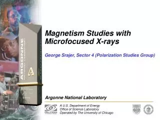
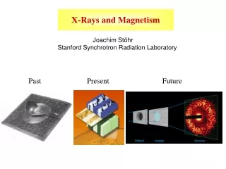
X-Rays and Magnetism Joachim Stöhr Stanford Synchrotron Radiation Laboratory Past Present Future
Present: Size > 0.1 mm, Speed > 1 nsec Future: Size < 0.1 mm, Speed < 1 nsec Ultrafast Nanoscale Dynamics
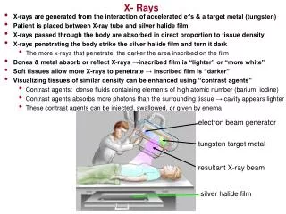
Non Resonant X-Ray Scattering Relative Intensity: 1 Relative Intensity: (hn / mc2)2 hn ~ 10 keV, mc2 = 500 keV
Fe metal – L edge Kortright and Kim, Phys. Rev. B 62, 12216 (2000) Soft X-Rays are best for magnetism!
Core level binding energies give: Element specificity Chemical state specificity
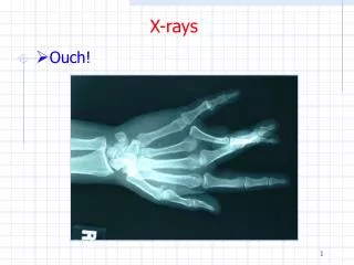
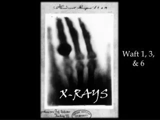
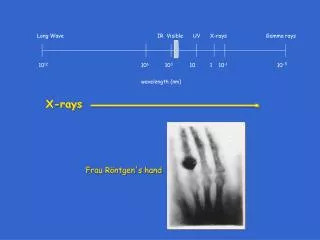
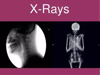
Part 1: Nanoscale Magnetism Real Space Imaging X-Rays have come a long way…… 1895 1993
PEEM-II at ALS • Full Field Imaging • Electrostatic (30 kV) • 20 - 50 nm Resolution • Linear and circular polarization
PEEM Contrast Mechanisms Use soft x-rays – L edges of Fe, Co, Ni
Exchange Bias – Exchange Coupling FM 1 FM 2 W AFM coercivity increase (uniaxial anisotropy) • exchange bias, loop shift (unidirectional anisotropy) A ferromagnet behaves different when in contact with an antiferromagnet. No appropriate understanding yet – 45 years after discovery Conventional techniques cannot study the magnetic interface
Co NiO
Co on NiO(001) Analysis of dichroism contrast 3 dimensional spin structure s s s [010] 2mm NiO after deposition 2nm Co on NiO(001) Bare NiO(001) Ni spins near antiferromagnetic surface rotate in-plane couple parallel to Co
s s [010] 2m m Spectromicroscopy of Ferromagnets and Antiferromagnets AFM domain structure at surface of NiO substrate FM domain structure inthin Co film on NiO substrate NiO XMLD Co XMCD H. Ohldag, A. Scholl et al., Phys. Rev. Lett. 86(13), 2878 (2001).
Interface Spectroscopy XAS Line shape is sensitive to transition M MxOy Upon Co deposition on NiO 2ML NiO Ni 2ML Co CoO Linear combination of metal and oxide spectra possible
Experiment 3:Interface Microscopy Co Co CoNiO NiO NiO AFM NiO FM Ni(O) FM Co XMLD XMCD XMCD Chemically induced interfacial spins provide the magnetic link
Bias polar +0.5% -0.5% azimuthal Loops of interfacial Mn spins Only a small fraction of interfacial spins is pinned Method Experiment Co/IrMn A small fraction (4%) of interfacial spins is pinned – they are the origin of exchange bias!
Exchange Bias: A new x-ray look at an old problem 4 crucial experiments 1.) The bare antiferromagnetic surface. F. U. Hillebrecht, H. Ohldag et al., Phys Rev. Lett. 86(15), 3419 (2001). 2.) The antiferromagnet surface coupled to a ferromagnet. H. Ohldag, A. Scholl et al., Phys. Rev. Lett. 86(13), 2878 (2001). 3.) The interface between both. H. Ohldag, A. Scholl et al., Phys Rev Lett. 87(24), 7201 (2001). 4.) Where are the pinned interfacial spins? To be published.
ideal AFM poly AFM Exchange Bias Model from X-Rays
A M D L L L O SM L L L L D S I L D X E The Future - PEEM-III • Aberration corrected PEEM • Estimated 2 nm resolution • Picosecond dynamics
Part 2: Ultrafast Magnetization Dynamics Switching with Exchange Fields Oersted fields Exchange fields Oersted fields are long range and weak Exchange fields are short range and strong
Magnetic Switching by Spin Injection • Nanoscale: <1000 Å • Both “in-plane” (black) and “out-of-plane” (red)
Proposed Solution • Use exchange field of injected spin current • Strong field, short pulse • Picosecond switching • Optimal at small sizes t0 t0 + t
Creating spin current • Spin moment relaxes into direction of bulk ferromagnet • Spin polarization reaches maximum at approximately 10 nm • Theoretically, spin polarization can be ~100% in some metals
FM NM current l is spin coherence length or spin flip length Polarization l Spin injection ~ 1 nm for ferromagnets (or 10 fs) ~ 1 µm for noble metals ( or 10 ps) ~ 100 µm for semiconductors (or 1 ns) X-ray experiments can observe: effect, size, sign and dynamics
Negative Damping by Spin Injection Minority spin injection
Nano-structure for Spin Injection 2 nm 1 – 1000 nm 30 nm 40 nm Focused Ion Beam Holes NiFe Cu Si3N4 Co • Current flows through Co to become spin polarized • Spin polarized current enters the NiFe layer changes the domain structure 1 µm Si3N4 PEEM microscopy
H Oersted Switching by Current through Contact Holes Fe 0.8 nm Cu 10 nm Si3N430 nm Cu 160 nm Current is not polarized, switching due to Oersted-like field 100 contact holes diameter 40 nmj 1012 A/m2 initial after 180 mA 10 mm 10-100 mm
Measuring Precession by Pump/Probe Technique Current pulse • Pump: induce spin polarization by current pulse • Probe: Image with delayed photon pulse • Vary the delay between current and photon pulse • Vary the strength of the current pulse 50 ps 330 ns Photon pulse
X-Ray FELs initial future ERLs Peak Brightness [Phot./(s · mrad2 · mm2 · 0.1%bandw.)] 3rd Gen. SR SPPS 2nd Gen. SR Laser Slicing FWHM X-Ray Pulse Duration [ps] Part 3: The Future X-Ray Free Electron Lasers
SASE gives 106 intensity gain • over spontaneous emission • FELs can produce ultrafast • pulses (of order 100 fs) l
LINAC COHERENT LIGHT SOURCE 0 Km 2 Km 3 Km
Concepts of the LCLS: • Based on single pass free electron laser (FEL) • Uses high energy linac (~15 GeV) to provide compressed electron beam to long undulator(s) (~120 m) • Based on SASE physics to produce 800-8,000eV (up to 24KeV in 3rd harmonic) radiation • Analogous in concept to XFEL of TESLA project at DESY
Proposed Schedule and Budget • FY2003-2004 • Prepare preliminary designs • FY2005 • Procure undulator • Construct injector • FY2006-2007 • Convert linac,install undulator, begin FEL commissioning • FY2008 • Complete civil construction, characterize photon beam • Estimated Total Project Cost : M$ 221 + M$ 47 = M$ 268
Example: Nanoscale Magnetism Reciprocal Space Imaging = Speckle Sample is non-periodic – no Bragg peaks
Nanoscale Magnetism PEEM versus SPECKLE PEEM – X-ray Absorption Speckle – Coherent X-ray Scattering • Photon-in / electron-out • Spatial resolution set by electron • optics • No strong external magnetic fields • Equilibrium dynamics: > 1msec • Pump-probe: no single shot – space charge limit • Photon-in / photon-out • Spatial resolution set by x-ray • wavelength: (775 eV) 16 Å) • Magnetic and electric fields • Equilibrium dynamics: > 1msec (now) • fsec (in future) • Pump-probe: • ultrafast and single shot Technique of choice for dynamics, future X-FELs Comparison to STXM: No zone plate optics -> less beam damage in FEL
scattering vector q (mm-1) scattering vector q (mm-1) 40 40 20 20 0 0 scattering vector q (mm-1) -20 -20 -40 -40 -40 -40 -20 -20 0 0 20 20 40 40 scattering vector q (mm-1) Incoherent vs. Coherent X-Ray Scattering Small Angle Scattering Coherence length larger than domains, but smaller than illuminated area information about domain statistics Speckle Coherence length larger than illuminated area true information about domain structure
Transmission X-ray Microscope Reconstruction from Speckle Intensities Imaging by Coherent X-Ray Diffraction Phase problem can be solved by “oversampling” speckle image 5 m (different areas) S. Eisebitt, M. Lörgen, J. Lüning, J. Stöhr, W. Eberhardt,E. Fullerton (unpublished)
Spin Block Fluctuations around Critical Temperature Tc Magnetization Temperature t = (T-Tc) / Tc T < Tc T Tc T > Tc
Collaborators Stanford Synchrotron Radiation Laboratory Hendrik Ohldag Christian Stamm Hans Christoph Siegmann Yves Acremann Advanced Light Source Andreas Scholl Frithjof Nolting (now SLS) Simone Anders (now IBM) Stanford University: Scott Andrews Bruce Clemens BESSY Stefan Eisebitt Marcus Lörgen Wolfgang Eberhardt IBM Almaden Erik Fullerton Charles Rettner Jan-Ulrich Thiele
Summary X-FELs will deliver: unprecedented brightness and femtosecond pulses Understanding of laser physics and technology well founded FELs promise to be extraordinary scientific tools Applications in many areas: chemistry, biology, plasma physics, atomic physics, condensed matter physics
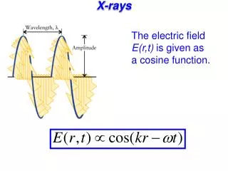
Fast Magnetization Dynamics is governed by Landau-Lifschitz-Gilbert equation: Angular momentum change Precession torque Gilbert damping torque 1 Tesla field: 90o rotation in 10 ps Typically a << 1, 100 ps We want to understand a on atomic level a controls switching time, a~1 optimal
Stoner Excitations: Changing the Magnetization by Electron Scattering