Practically Realizing Random Access Scan
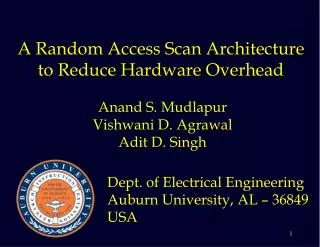
Practically Realizing Random Access Scan. Anand S. Mudlapur. Department of Electrical and Computer Engineering Auburn University, AL 36849 USA. Motivation for This Work. Serial scan (SS) test sequence lengths and test power consumption are increasing rapidly.


Practically Realizing Random Access Scan
E N D
Presentation Transcript
Practically Realizing Random Access Scan Anand S. Mudlapur Department of Electrical and Computer Engineering Auburn University, AL 36849 USA
Motivation for This Work • Serial scan (SS) test sequence lengths and test power consumption are increasing rapidly. • Reduction of test power and test time are complementary objectives in serial scan. • Scope of increasing delay fault coverage is limited in serial scan. • In spite of the advantages (test time, test volume, test power, and ease of testing for delay faults), random access scan (RAS) is not popular due to high overhead. MS Thesis Defence
Outline • Introduction to scan based testing • Advantages • Limitations • Introduction to RAS • Design of a new toggle RAS Flip-Flop • Highlight the uniqueness and feasibility of our design due to the reduction of two global signals MS Thesis Defence
Outline (contd.) • A new scan-out structure • Analytical formulation of hardware overhead • Algorithm to compact test vectors • ATPG targeted for toggle RAS • Results on ISCAS Benchmark Circuits • Case study on an industrial circuit • Conclusion and future work MS Thesis Defence
Serial Scan: Most Popular DFT Method Combinational Circuit PI PO Scan-in Scan-out FF FF FF Test control (TC) MS Thesis Defence
Introduction to Serial Scan (contd.) • Advantage: Enables application of combinational vectors to sequential circuits • Problems: • Clock cycles prohibitive as number of flip-flops increases • Scan-in often performed at a slow scan clock compared to functional clock of the circuit • Scan-in and scan-out cause undesirable circuit activity resulting in excessive power dissipation MS Thesis Defence
Test Power and Time of Serial Scan • Test power may exceed critical design limits. • All flip-flops are controlled and observed although a test may need those operation only on a subset of flip-flops. • Example: A circuit with 5,000 Flip-Flops and 10,000 combinational test vectors Total scan cycles = 5,000 × 10,000 + 10,000 + 5,000 = 50,015,000 ! MS Thesis Defence
Solutions for Test Time Problem of Serial Scan • Partial scan [Agrawal et. al. 88] provides a trade off between ease of test generation and hardware cost of scan. Test power may still be a concern. • Vector compaction [Touba et. al. 00], may cause increased circuit activity resulting in higher power consumption. • Cross-Check [Gheewala et. al. 91] was a comprehensive test method for sequential circuits but the technology required dedicated routing layers for test wiring. MS Thesis Defence
A grid architecture as shown in the adjoining figure Flip-flops contents read out row-wise Data from the flip-flops fed into a MISR Cross-Check MS Thesis Defence
Solutions for Test Power Problems of Serial Scan • Test scheduling for SOCs using power constraint [Chou et. al. 91]: Test parallelism reduces, increasing the test time. • Slow scan-clock [Chandra et. al. 94]: Test time increases. • ATPG based methods [Wang et. al. 94, Kajihara et. al. 02]: Result in lengthy test sequences. Contd. MS Thesis Defence
Further Solutions for Test Power (contd.) • Modification of the order of scan cells or inserting inversion logic between scan cells after the test generation [Dabholkar et al. 98]; limited effect on test power. • Blocking hardware methods: Hold latch, blocking gates; have additional overhead. MS Thesis Defence
Delay Testing in Serial Scan • Delay testing in serial scan is highly constrained; may result in low fault coverage. • Enhanced scanflip-flops can make the application of arbitrary vectors possible. • This technique requires a hold-latch connected to each Flip-Flop in addition to a “HOLD” signal routed to every hold latch resulting in increased area overhead and signal delay in the scan path. MS Thesis Defence
Delay Testing in Serial Scan Combinational Circuit PI PO CK Scan-out CK TC HOLD HL SFF V1 settles TC Scan-out V1 s-in V2 state scan-in HL SFF Test result latched Scan-in HOLD V1 V2 CK TC MS Thesis Defence
Introduction to RAS • Random Access Scan (RAS) offers a single solution to the problems faced by serial scan (SS): • Each RAS cell is uniquely addressable for read and write. • RAS addresses both test application time and test power problems simultaneously • Previous and current publications on RAS: • Ando, COMPCON-80 • Wagner, COMPCON-83 • Ito, DAC-90 • Baik et al., VLSI Design-04, ITC-05, ATS-05, VLSIDesign-06 • Mudlapur et al., VDAT-05, ITC-05 • Disadvantage: High routing overhead – test control, address and scan-in signals must be routed to all flip-flops. MS Thesis Defence
Contributions of Present Work • Eliminate scan-in signal from circuit by using a new toggling RAS flip-flop. • Eliminate test control signal to flip-flops. • Provide a new scan-out architecture: • A hierarchical scan-out bus • An option of multi-cycle scan-out MS Thesis Defence
Random Access Scan (RAS) Combinational Circuit PI PO Address Inputs FF FF FF Scan-out bus Decoder Scan-in These signals are eliminated in our design TC During every test, only a subset of all Flip-flops needs to be set and observed for testing the targeted faults MS Thesis Defence
Conventional RAS Combinational Logic Data Combinational Logic Data M S M U X M U X Scan-in Clock Mode RAS-FF Address Decoder Address Register ACLK MS Thesis Defence
New “Toggle” RAS Flip-Flop Combinational Logic Data 1 M S To Output BUS M U X Combinational Logic Data 0 Clock Output BUS Control x y RAS-FF √nff Lines √nff Lines Row Decoder Column Decoder Address (log2nff) MS Thesis Defence
Toggle RAS Flip-Flop Operation MS Thesis Defence
Toggle Flip-Flop Operation (contd.) Unaddressed FFs Addressed FF RAS FF 0 RAS FF 1 RAS FF 1 RAS FF 0 x4 Decoded address lines y1 y2 y3 MS Thesis Defence
Macro Level Idea of Signals to RAS-FF 4-to-1 Scan-out Macrocell RAS FF11 RAS FF11 RAS FF12 RAS FF12 RAS FF13 RAS FF13 RAS FF14 RAS FF14 x1 RAS FF21 RAS FF22 RAS FF22 RAS FF23 RAS FF24 x2 RAS FF31 RAS FF32 RAS FF33 RAS FF34 x3 RAS FF41 RAS FF42 RAS FF43 RAS FF44 To Next Level x4 MS Thesis Defence y1 y2 y3 y4
Scan-out Macrocell • A 4x4 block scan-out data flow and control logic • D-FFs may be inserted at the two outputs of macrocell for multi-cycle scan-out. Data Bus From 4 RAS FFs To Next Level Output BUS { Control Signal to Next Level BUS Control From 4 RAS FFs MS Thesis Defence
Routing of Decoder Signals in RAS Address (log2 √nff) Flip-Flops Placed on a Grid Structure R O W D E C O D E R Address (log2 √nff) COLUMN DECODER MS Thesis Defence
Gate Area Overhead Gate area overhead of Serial Scan = Gate area overhead of Random Access Scan = where nff – Number of Flip-Flops ng – Number of Gates Assumption: D-FF contains 10 logic gates. MS Thesis Defence
Gate Area Overhead (Examples) 1. A circuit with 100,000 gates and 5,000 FFs Gate overhead of serial scan = 13.3 % Gate overhead of RAS = 20.0 % (Typical example from an industrial circuit. Details in later slide) 2. A circuit with 500,000 gates and 5,000 FFs Gate overhead of serial scan = 3.6 % Gate overhead of RAS = 5.5 % MS Thesis Defence
Overhead in Terms of Transistors Transistor overhead of Serial Scan = Transistor overhead of Random Access Scan = Where nt is number of transistors in comb. logic. D-flip-flop (28 transistors), serial scan FF (28+10) and RAS FF (28+26) were designed in 0.5μ CMOS technologyusing Mentor Graphics Design Architect. MS Thesis Defence
Algorithm to Compact Test Vectors • Obtain the combinational vectors along with good circuit responses and store the results in a stack • Find the Flip-Flops where the faults are propagated at each vector • While number of vectors > 0 or remaining faults > 0 • Read all Flip-Flops where the faults are detected • Choose the next vector from stack that is at least hamming distance from current Flip-Flop states • End While MS Thesis Defence
Compaction of Test Vectors Stack 101 000 010 110 111 100 001 100 Combinational Circuit PI PO Address Inputs RAS-FF RAS-FF RAS-FF RAS-FF 0 1 0 0 1 0 Scan-out bus Decoder MS Thesis Defence
Test Time MS Thesis Defence
Test Power MS Thesis Defence
Case Study on an Industrial Circuit • A case study on an industry circuit was performed at Texas Instruments India Pvt. Ltd. • The preliminary results were as follows: • The gate area overhead of RAS for a chip with ~5500 Flip-Flops and ~100,000 NAND equivalent gates was of the order of 18%. • 4X reduction in test time was estimated. A speed-up of up to 10X was considered possible using ATPG heuristics. • Estimated routing and device area overhead of RAS in physical layout was 10.4%. MS Thesis Defence
Conclusion • New design of a “Toggle” Flip-Flop reduces the RAS routing overhead. • Proposed RAS architecture with new FF has several other advantages: • Algorithmic minimization reduces test cycles by 60%. • Power dissipation during test is reduced by 99%. • A novel RAS scan-out method presented. • For details on “Toggle” Flip-Flop, see Mudlapur et al., VDAT-05. MS Thesis Defence
Backup Slides MS Thesis Defence